EasyManuals Logo

JVC RX-D201 User Manual

JVC RX-D201
105 pages
To Next Page IconTo Next Page
To Previous Page IconTo Previous Page
Page #9 background imageLoading...
Page #9 background image
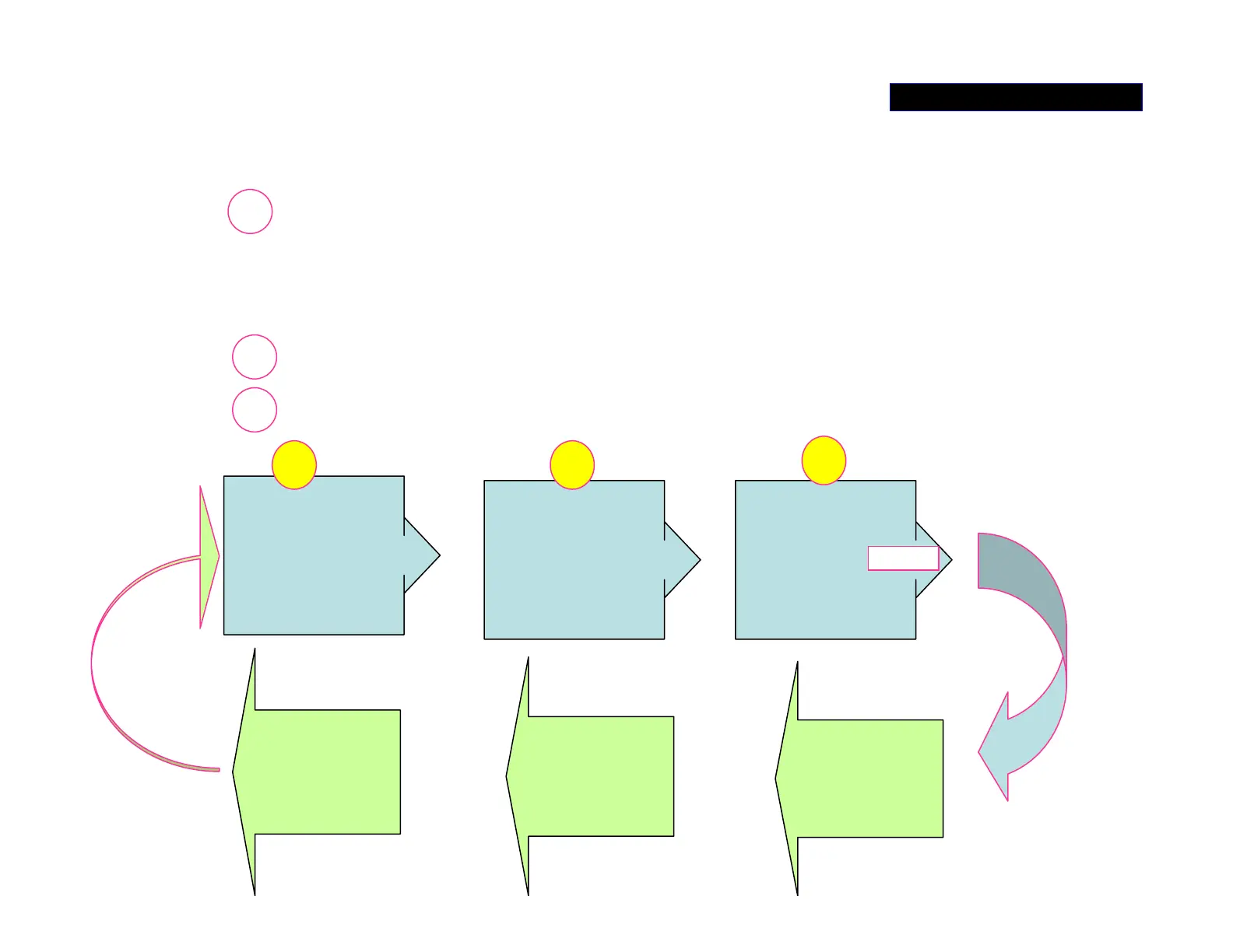
The ‘AMP_+/-B’ switch regulator
composes three sections:
1. MOSFET switch circuit (the important parts are
Q1101/1102, D1107/1108, L1101/1102,
C1117/1118…)
2. Switch driver circuit-IC101.
3. DC-DC Converter Control Board
DC-DC
CONVERTER
CONTROL
MOSFET
DRIVE
IC101
+
MOSFET
SWITCH
Q1101/1102…
_
1
3 2
AMP_B
7 CHANNEL
POWER
AMP
AMP_ +/-B
LEVEL
CONTROL
CPU IC501
SOUND
LEVEL
DETECT
POWER SUPPLY 3/5

Questions and Answers:

Question and Answer IconNeed help?

Do you have a question about the JVC RX-D201 and is the answer not in the manual?

JVC RX-D201 Specifications

General IconGeneral
BrandJVC
ModelRX-D201
CategoryReceiver
LanguageEnglish

Related product manuals