1-18 (No.MB364)
3.2 Front panel assembly section
• Remove the front panel assembly.
(See "3.1.2 Removing the front panel assembly".)
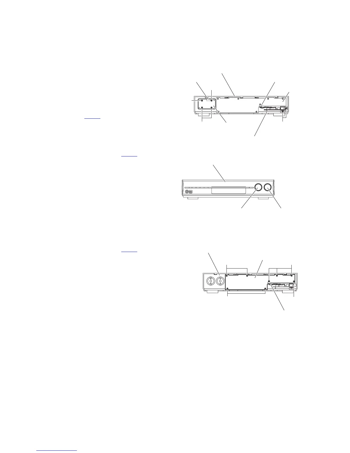
3.2.1 Removing the JOG board
(See Figs.1 and 2)
(1) From the inside of the front panel assembly, remove the
four screws A attaching the JOG board. (See Fig.1.)
(2) Take out the JOG board while lifting it from the front panel
assembly little by little.
Reference:
The master volume knob and MULTI JOG knob are re-
moved from the front side simultaneously. (See Fig.2.)
(3) From the forward side of the JOG board, disconnect the
wire from the connector CN913
. (See Fig.1)
3.2.2 Removing the OSD connect 2 board
(See Fig.1)
(1) From the inside of the front panel assembly, remove the
two screws A attaching the OSD connect 2 board.
(2) Disconnect the wire from the connector CN914
on the FL
board.
Fig.1
Fig.2
3.2.3 Removing the FL board
(See Fig.3)
• Remove the JOG board.
(1) Disconnect the wire from the connector CN914 on the FL
board.
(2) Remove the eight screws A and take out the FL board.
Fig.3
CN913
A
A
A
Front panel assembly
CN914
FL board
A
OSD connect 2 board
JOG board
Front panel assembly
MULTI JOG knob
Master volume knob
A
A
Front panel assembly
CN914
FL board
A
A

 Loading...


