1-12 (No.MB448)
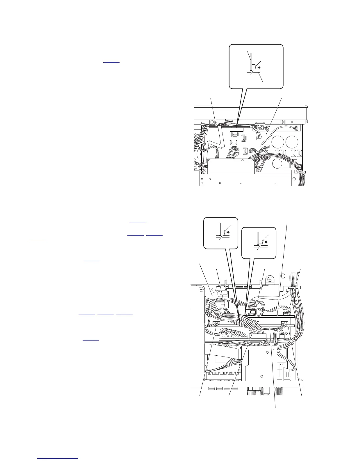
3.1.13 Removing the DCDC control board
(See Fig.10)
• Remove the top cover.
From the top side of the main body, disconnect the DCDC control
board from the main amplifier board in an upward direction while
releasing the claw g of the connector CN152
on the main ampli-
fier board.
Note:
When releasing the claw g, take care not to break it.
Fig.10
3.1.14 Removing the PWM modulation 1 board
(See Fig.11)
• Remove the top cover.
(1) Disconnect the wire from the connector CN413
on the
PWM modulation 2 board.
(2) Disconnect the wires from the connectors (CN311
, CN312,
CN313) on the PWM modulation 1 board.
(3) Disconnect the PWM modulation 1 board from the main
amplifier board in an upward direction while releasing the
claw h of the connector CN302
on the main amplifier board.
Note:
When releasing the claw h, take care not to break it.
3.1.15 Removing the PWM modulation 2 board
(See Fig.11)
• Remove the top cover.
(1) From the top side of the main body, disconnect the wires
from the connectors (CN411
, CN412, CN413) on the PWM
modulation 2 board.
(2) Disconnect the PWM modulation 2 board from the main
amplifier board in an upward direction while releasing the
claw j of the connector CN402
on the main amplifier board.
Note:
When releasing the claw j, take care not to break it.
Fig.11
Main amplifier board
Main amplifier board
DCDC control board
CN152
g
DCDC control board
CN312
Main amplifier
board
CN302
h
CN402
j
CN313 CN311
CN411CN413CN412
PWM modulation 1 board
PWM modulation 2 board
 Loading...


