(No.MB448)1-11
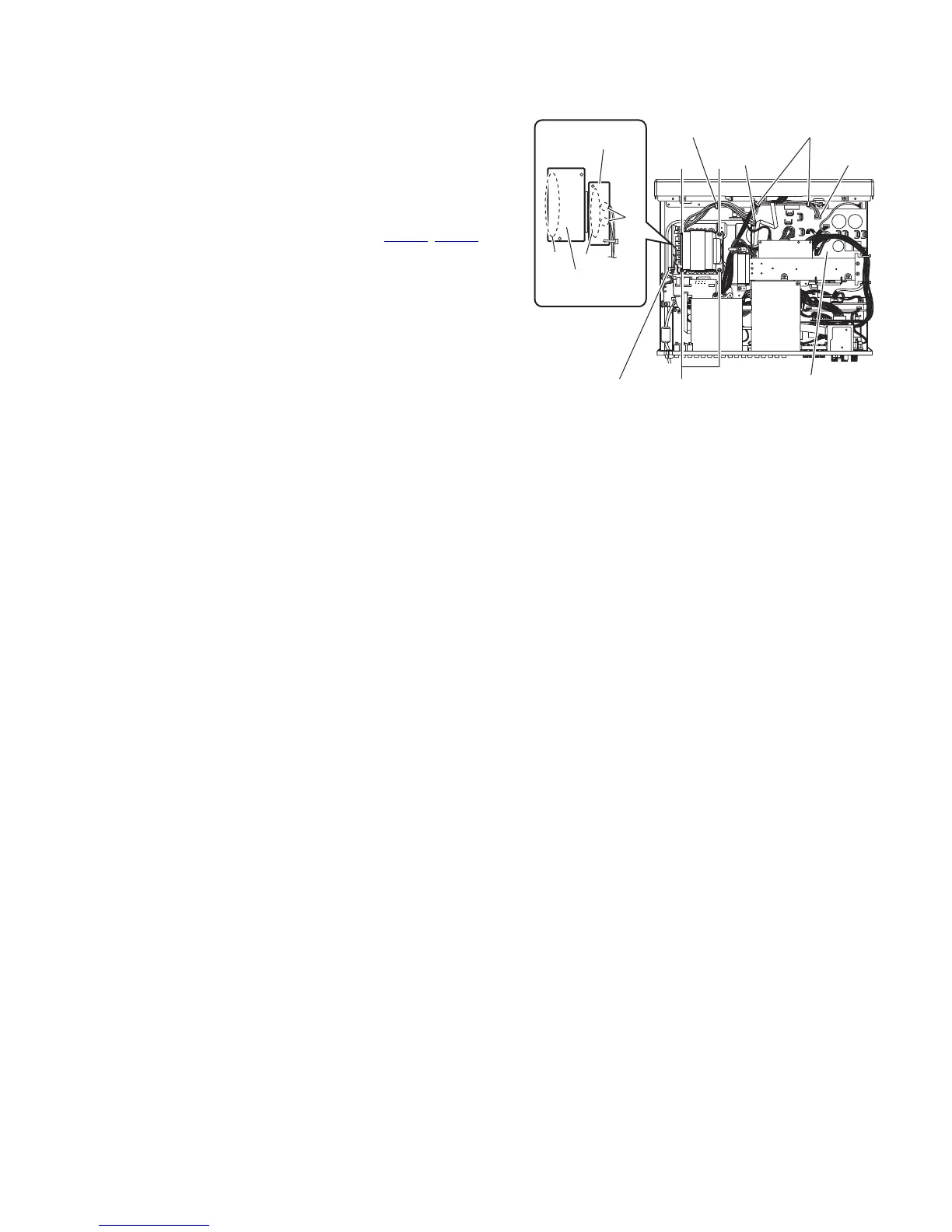
3.1.10 Removing the power transformer
(See Fig.9)
• Remove the top cover.
(1) From the top side of the main body, remove the tie band
bundling the wires.
Reference:
After reassembling, bundle the wires with a new tie band
as before.
(2) Release the wire holders to remove the wires.
(3) Disconnect the wires from the connectors (CN106
, CN111)
on the main amplifier board.
(4) Remove the soldered sections d and remove the wires.
(5) Remove the four screws S and take out the power trans-
former from the main body.
3.1.11 Removing the trans primary board
(See Fig.9)
• Remove the top cover.
(1) From the top side of the main body, remove the tie band
bundling the wires.
Reference:
After reassembling, bundle the wires with a new tie band
as before.
(2) Remove the wires from the soldered sections d and re-
move the wires.
(3) Remove the solders from the soldered sections e and re-
move the trans primary board.
3.1.12 Removing the trans secondary board
(See Fig.9)
• Remove the top cover.
Reference:
Take out the power transformer from the main body as re-
quired.
From the side of the power transformer, remove the solders from
the soldered sections f and remove the trans secondary board.
Fig.9
f
S
CN106 CN111
Wire holder
Tie band
S
S
e
d
Trans primary
board
Trans secondary
board
Main amplifier board
Wire holders
 Loading...


