1-10 (No.MB448)
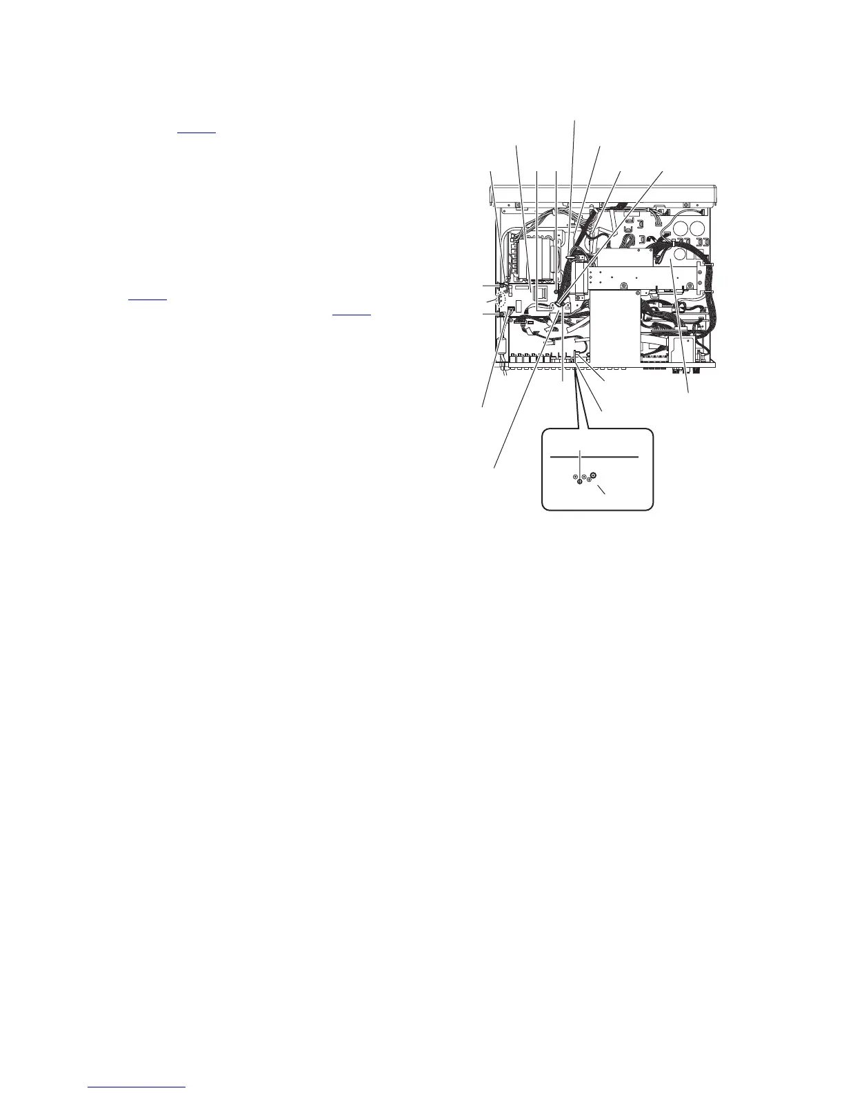
3.1.8 Removing the compulink board
(See Fig.8)
• Remove the top cover and HDMI board.
(1) From the top side of the main body, disconnect the wire
from the connector CN565 on the compulink board.
(2) From the back side of the main body, remove the screw P
attaching the compulink board to the rear panel and take
out the compulink board.
3.1.9 Removing the primary board
(See Fig.8)
• Remove the top cover and HDMI board.
(1) From the top side of the main body, remove the screw Q
attaching the support bracket on the chassis base.
(2) Release the wire holders and disconnect the wire from the
connector CN101
on the main amplifier board.
(3) Disconnect the power cord from the connector CN120 on
the primary board.
(4) Remove the two screws R and two screws R' attaching the
primary board.
Reference:
When attaching the screws R', attach the wire holders
with them as before.
(5) Take out the primary board from the main body and remove
the wires from the soldered sections c on the reverse side
of the primary board.
Fig.8
R'
R
c
R' R
Q
P
Compulink board
Rear panel
Wire holder
CN120
Support bracket
Main amplifier board
Wire holderCN101
Wire holder
Chassis base
Primary board
CN565
 Loading...


