(No.MB448)1-9
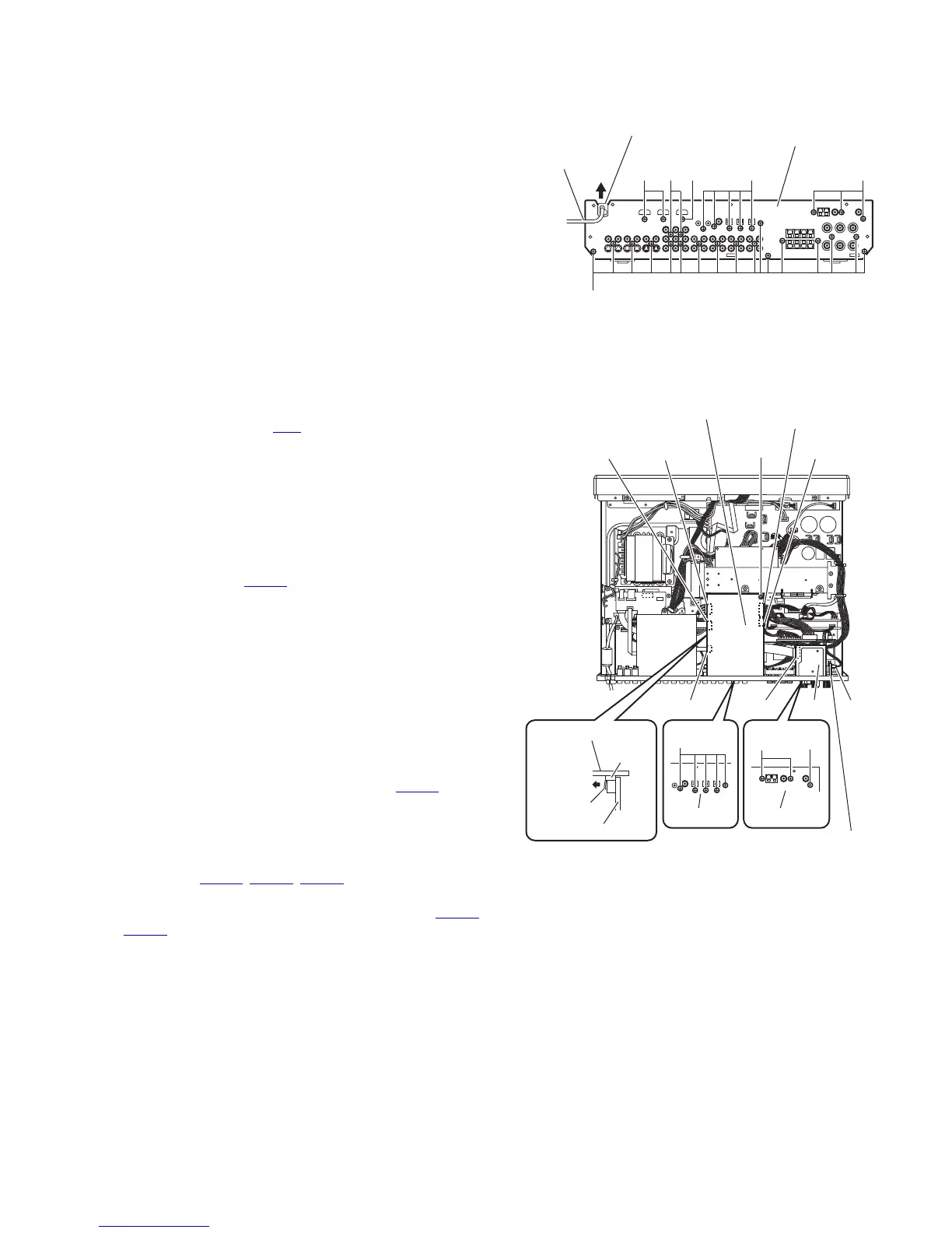
3.1.4 Removing the rear panel
(See Fig.6)
• Remove the top cover.
(1) From the back side of the main body, remove the strain re-
lief from the rear panel in the direction of the arrow and re-
move the power cord.
(2) Remove the three screws G and twenty-seven screws H
attaching the rear panel.
Fig.6
3.1.5 Removing the tuner
(See Fig.7)
• Remove the top cover.
(1) From the top side of the main body, disconnect the card
wire from the connector CN1
on the tuner.
(2) From the back side of the main body, remove the two
screws J attaching the tuner to the rear panel and take out
the tuner.
3.1.6 Removing the subwoofer board
(See Fig.7)
• Remove the top cover.
(1) From the top side of the main body, disconnect the wire
from the connector CN524
on the subwoofer board.
(2) From the back side of the main body, remove the screw K
attaching the subwoofer board to the rear panel and take
out the subwoofer board.
3.1.7 Removing the DSP board
(See Fig.7)
• Remove the top cover.
(1) From the back side of the main body, remove the five
screws M attaching the DSP board to the rear panel.
(2) Remove the screw N attaching the DSP board.
(3) Disconnect the DSP board from the DSP connect board
while releasing the claw b of the connector CN681
on the
DSP board.
Note:
When releasing the claw b, take care not to break it.
(4) Take out the DSP board and disconnect the wires from the
connectors (CN661
, CN682, CN683) on the forward side of
the DSP board.
(5) Disconnect the card wires from the connectors (CN651
,
CN652
) on the forward side of the DSP board.
Fig.7
Strain relief
H
Rear panel
Power cord
G HHG H
N
CN682
CN683
DSP board
CN661CN652
CN651 Tuner
Rear panel Rear panel
CN1 CN524
Subwoofer board
KJ
M
CN681
DSP board
b
DSP connect board