(No.MB448)1-15
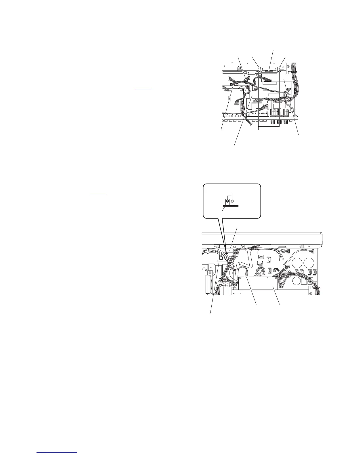
3.1.21 Removing the master clock board
(See Fig.16)
• Remove the top cover, tuner, DSP board, PWM modulation 1
board, PWM modulation 2 board and OSD connect 1 board.
(1) From the top side of the main body, remove the tie band
bundling the wires.
Reference:
After reassembling, bundle the wires with a new tie band
as before.
(2) Disconnect the wire from the connector CN201
on the main
amplifier board.
(3) Remove the two screws W with a short driver and remove
the transistor hold from the joints n of the heat sink.
(4) Take out the master clock board from the main body.
Fig.16
3.1.22 Removing the HDMI-Regulator board
(See Fig.17)
• Remove the top cover.
(1) From the top side of the main body, disconnect the wire
from the connector CN117
on the forward side of the regu-
lator board.
(2) Remove the two screws X attaching the HDMI-Regulator
board on the chassis base.
(3) Take out the HDMI-Regulator board from the main body.
Fig.17
W
n
n
Tie band
Transistor hold
Master clock board
Main amplifier board
CN201
HDMI-Regulator board
CN117
Regulator board
Chassis base
X
HDMI-Regulator board