1-16 (No.MB448)
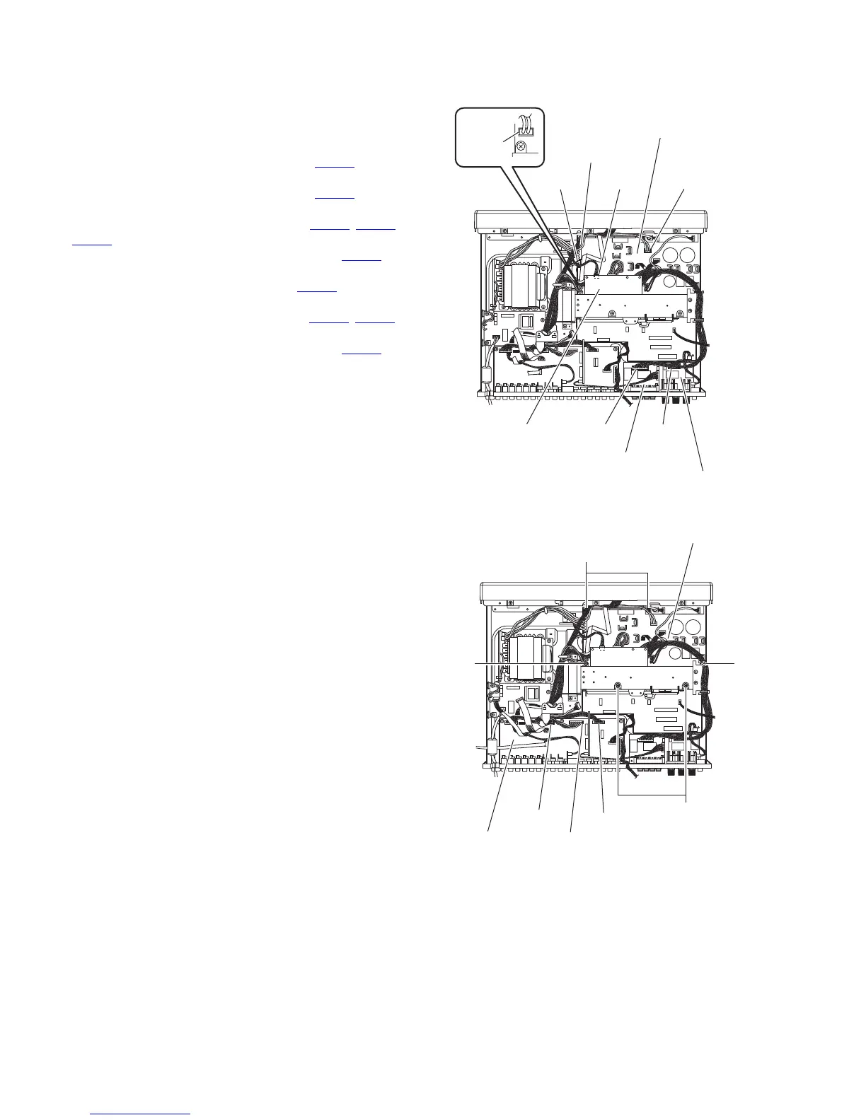
3.1.23 Removing the main amplifier board
(See Figs.18 and 19)
• Remove the top cover, HDMI board, front panel assembly, tun-
er, DSP board, DCD control board, PWM modulation 1 board,
PWM modulation 2 board, OSD connect 1 board and master
clock board.
(1) Disconnect the wire from the connector CN265
on the
speaker terminal 1 board. (See Fig.18.)
(2) Disconnect the wire from the connector CN262
on the
speaker terminal 2 board. (See Fig.18.)
(3) Disconnect the wires from the connectors (CN103
, CN106,
CN111
) on the main amplifier board. (See Fig.18.)
(4) Disconnect the parallel wire from the connector CN101
on
the main amplifier board. (See Fig.18.)
(5) Disconnect the wire from the connector CN117
on the for-
ward side of the regulator board. (See Fig.18.)
(6) Disconnect the wires from the connectors (CN530
, CN531)
on the input board. (See Fig.19.)
(7) Disconnect the parallel wire from the connector CN540
on
the input board. (See Fig.19.)
(8) Remove the four screws Y and two screws Z. (See Fig.19.)
(9) Take out the main amplifier board with the regulator board
from the main body. (See Fig.19.)
Fig.18
Fig.19
CN106
Main amplifier board
CN101 CN117
CN103
CN111
CN265
Speaker terminal 1 board
CN262Regulator board
Speaker terminal 2 board
Main amplifier board
CN540
Z
Y
Y
CN530
CN531
Input board