(No.MB448)1-17
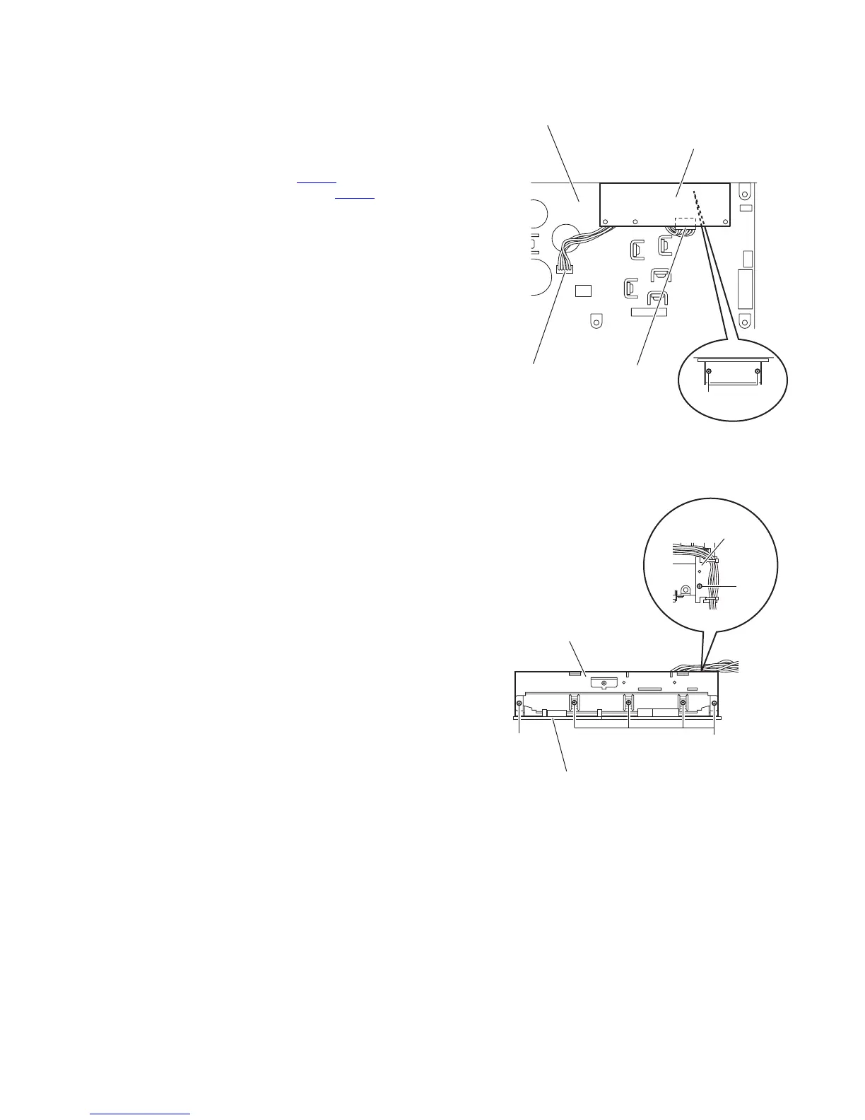
3.1.24 Removing the regulator board
(See Fig.20)
• Remove the top cover, HDMI board, front panel assembly, tun-
er, DSP board, DCD control board, PWM modulation 1 board,
PWM modulation 2 board, OSD connect 1 board, master clock
board and main amplifier board.
(1) From the forward side of the main amplifier board, discon-
nect the wire from the connector CN105
.
(2) Disconnect the wire from the connector CN114
on the reg-
ulator board.
(3) Remove the two screws AA attaching the regulator board.
Fig.20
3.1.25 Removing the heat sink
(See Fig.21)
• Remove the top cover, HDMI board, front panel assembly, tun-
er, DSP board, DCD control board, PWM modulation 1 board,
PWM modulation 2 board, OSD connect 1 board, master clock
board and main amplifier board.
(1) From the forward side of the main amplifier board, remove
the screw AB and remove the wire holder board with the
wires.
(2) Remove the five screws AC to remove the heat sink.
Fig.21
AA
CN105
Regulator board
Main amplifier board
CN114
Heat sink
AC
Main amplifier board
AC
Wire holder board
AB