RX-DP10VBK/RX-DP10VSL
RX-DP10RSL
1-20
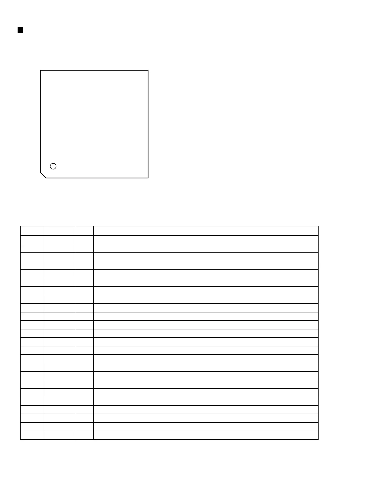
1. Pin layout
JCV8006 (IC635, IC640, IC645, IC650) : CC converter
VDD
FP1
FP2
WSN
WS
RAMT
VSS
CLK
VDD
DFR1
DFR2
DF1
DF2
DFSEL
SH
VSS
VDD
VCK
DIN
LRCK
CAD1
CAD0
RESET
VSS
MODE
MCK/IW2N
MDT/IW1N
MLEN/IOF
BT
D1W1
D1W2
VSS
VSS
TOUT6
TOUT7
TOUT8
TOUT9
TOUTA
TOUTD
VDD
TMD0
TMD1
CKSLN
PDN
CKDV
F192
TSTEN
VDD
VSS
TOUT0
TOUT1
TOUT2
DOUT1
BCKO1
WCKO1
VDD
VSS
DOUT2
BCKO2
WCKO2
TOUT3
TOUT4
TOUT5
VDD
49
50
51
52
53
54
55
56
57
58
59
60
61
62
63
64
1
2
3
4
5
6
7
8
9
10
11
12
13
14
15
16
32
31
30
29
28
27
26
25
24
23
22
21
20
19
18
17
48
47
46
45
44
43
42
41
40
39
38
37
36
35
34
33
2. Pin function (1/2)
Pin name
VDD
BCK
DIN
LRCK
CAD1
CAD0
RESET
VSS
MODE
MCK/IW2N
MDT/IW1N
MLEN/IOF
BTR
D1W1
D1W2
VSS
VDD
TSTEN
F192
CKDV
I/O
-
l1
l1
l1
lp2
lp2
l1
-
lp2
l1
l1
l1
lp2
lp2
lp2
-
-
lp2
lp2
lp2
Function
Power supply : All VDD pins must be connected externally
Bit clock input :Bit click if serial data into the DIN ; Must run continuously, "5V tolerant"
Serial audio data input, "5V tolerant"
Left/Right clock input ; sampling frequency (fs) for DIN ; Must run continuously, "5V tolerant"
Chip address 1 ; available on MODE=H
Chip address 0 ; available on MODE=H
System reset ; the internal state is reset to the default setting when L, "5V tolerant"
Ground ; All VSS pins must be connected externally
System control mode select input : (H=Software mode ; L=Hardware mode)
Control clock input ; MODE=H,
/Select input audio data word length input2 ; MODE=L, "5V tolerant"
Control data input ; MODE=H,
/Select input audio data word length input 1 ; MODE=L, "5V tolerant"
Control data latch input ; MODE=H,
/select input and output audio data format input ; MODE=L, "5V tolerant"
Select BIT-UP through mode input ; MODE=L
Select output 1 audio data word length and enable control 1 ; MODE=L
Select output 1 audio data word length and enable control 2 ; MODE=L
Ground ; All VSS pins must be connected externally
Power supply ; All VSS pins must be connected externally
Test control input ; in normal operation this pin should be terminated to ground
Select system clock for 192kHz input sampling frequency input : MODE=L,
(supported for FS-UP only)
Internal click divider select input ; MODE=L,(L=1, H=1/2)
Pin No.
1
2
3
4
5
6
7
8
9
10
11
12
13
14
15
16
17
18
19
20
l=CMOS, l1=Schmitt, lp2=Schmitt with pull-down resistor, O=CMOS (H=VDD, L=VSS)