EN 85
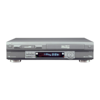
Rear panel
1 AC power cord : pg. 7
2 Cooling fan
● This prevents the temperature from rising inside the
VCR. Do not remove it.
● Install the VCR so as not to block the area around
the cooling fan.
3 JLIP terminal : pg. 65
4 Component video output connectors : pg. 8
5 ANTENNA IN terminal : pg. 7
6 i.LINK IN/OUT, DV IN Connector (i.Link*)
: pg. 66
* i.Link refers to the IEEE1394-1995 industry specifi-
cation and extensions thereof. The
logo is used for
products compliant with the i.Link standard.
S400
DV IN
D THEATER
REGION 1
i.LINK IN/OUT
DIGITAL OUT
OPTICAL
PCM/DOLBY DIGITAL
R
Y
L
P
B
/C
B
VIDEO
P
R
/C
R
S VIDEO
S VIDEO
AUDIO
IN
(L-1)
IN
(L-2)
REMOTE PAUSE/
AV COMPULINK
CABLE BOX
ANTENNA
ANTENNA
OUT
IN
VHF/UHF
R
L
VIDEO
AUDIO
OUT
IN
COMPONENT
VIDEO OUT
#@!0978
2456
3
1
7 CABLE BOX Controller connector :
pg. 15, 18
8 REMOTE PAUSE/AV COMPULINK terminal
● REMOTE PAUSE terminal : pg. 69
● AV COMPULINK terminal : pg. 60
9 S VIDEO/AUDIO/VIDEO OUT connectors :
pg. 7, 8, 68
0 S VIDEO/AUDIO/VIDEO IN connectors (L-2):
pg. 68
! S VIDEO/AUDIO/VIDEO IN connectors (L-1):
pg. 68
@ ANTENNA OUT terminal : pg. 7
# DIGITAL OUT OPTICAL terminal : pg. 57
VD400U-EN74-91 03.7.18, 1:12 PM85

 Loading...