(No.MB141)1-11
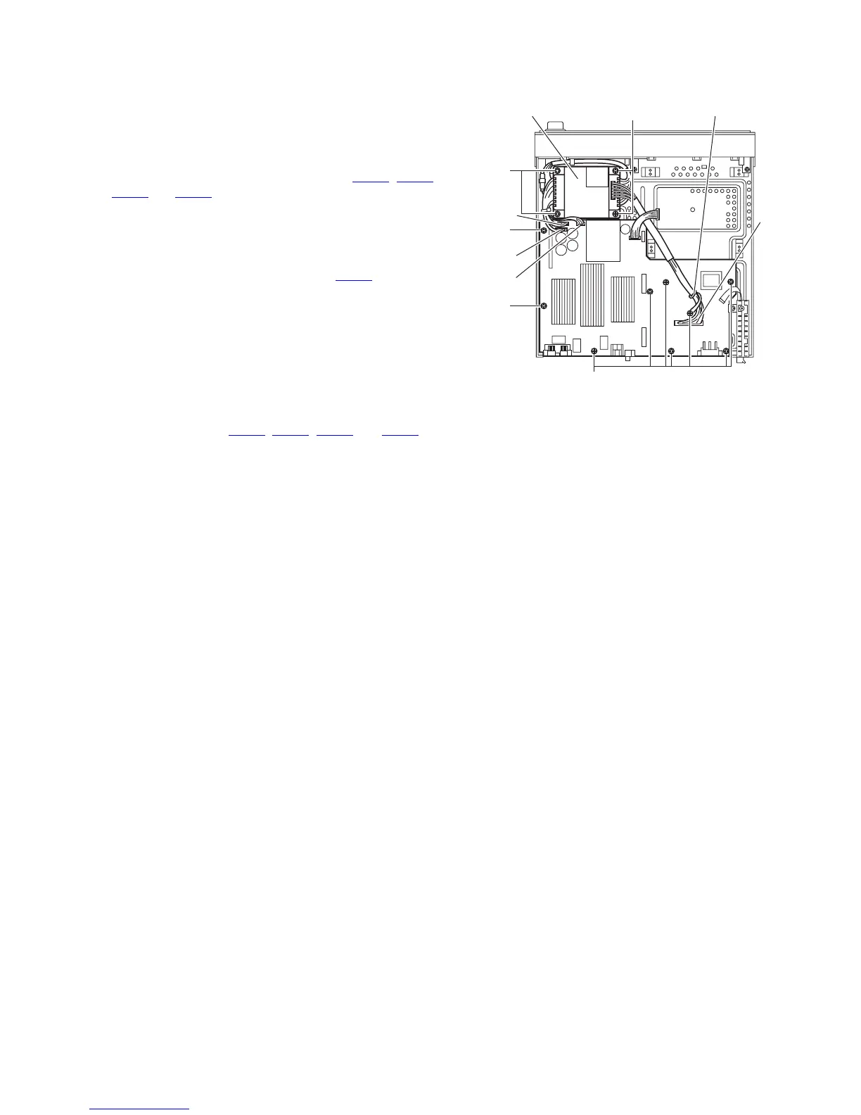
3.1.10 Removing the main board
(See Fig.14)
• Prior to performing the following procedures, remove the top
cover, tray door, DVD mechanism assembly, fan motor, rear
panel, video board and function board.
(1) From the top side of the main body, remove the nine
screws P attaching the main board.
(2) Disconnect the wires from the connectors ACW2
, ACW3,
ACW4
and ACW5 on the main board and take out the main
board.
Reference:
• When attaching the screw P, attach the wire clamp together
with it.
• After connecting the wire to the connector ACW2
, bundle the
wire using the wire clamp.
3.1.11 Removing the power trans
(See Fig.14)
• Prior to performing the following procedures, remove the top
cover, tray door, DVD mechanism assembly, fan motor, rear
panel, video board and function board.
(1) From the top side of the main body, disconnect the wires
from the connectors ACW2
, ACW3, ACW4 and ACW5 on
the main board.
(2) Remove the four screws Q attaching the power trans.
Fig.14
Power trans
CW5
CW4
CW3
ACW2
P
Q
P
Q
P
Wire clamp