(No.MB141)1-9
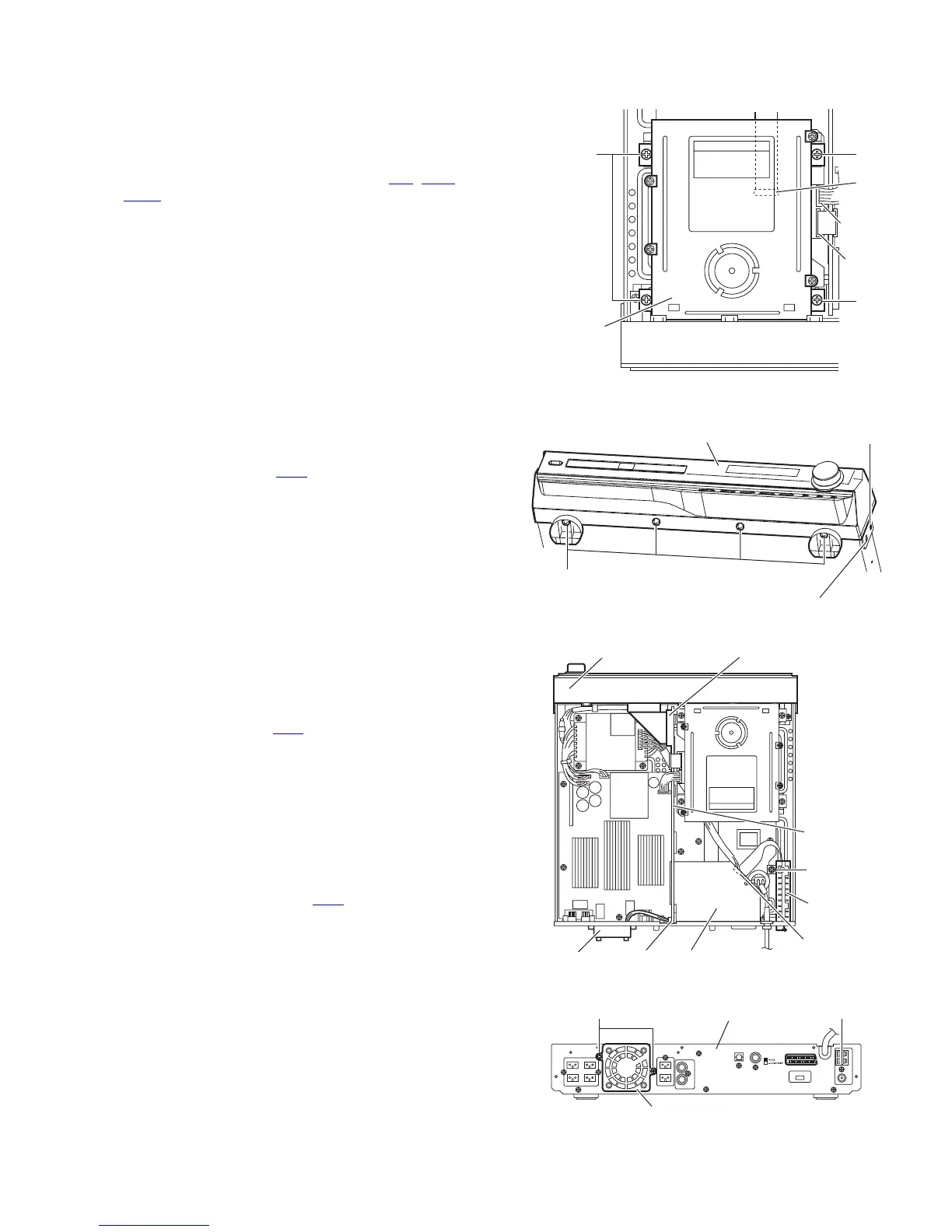
3.1.3 Removing the DVD mechanism assembly
(See Fig.7)
• Prior to performing the following procedures, remove the top
cover and tray door.
(1) From the top side of the main body, remove the four screws
D attaching the DVD mechanism assembly.
(2) Disconnect the wires from the connectors AJ1
, AJS1 and
PCN1 on the DVD mechanism assembly, and take out the
DVD mechanism assembly.
Fig.7
3.1.4 Removing the front panel assembly (See Figs.8 and 9)
• Prior to performing the following procedures, remove the top
cover and tray door.
(1) From the top side of the main body, disconnect the card
wire from the connector UW4
on the function board. (See
Fig.8)
(2) From the bottom side of the main body, remove the four
screws E attaching the front panel assembly. (See Fig.9)
(3) From the both sides of the main body, remove the two
screws F attaching the front panel assembly. (See Fig.9)
(4) Release the joints d in forward direction and take out the
front panel assembly. (See Fig.9)
3.1.5 Removing the tuner pack
(See Figs.8 and 10)
• Prior to performing the following procedures, remove the top
cover.
(1) From the top side of the main body, disconnect the card
wire from the connector VW4
on video board. (See Fig.8)
(2) Remove the screw G attaching the tuner pack. (See Fig.8)
(3) From the back side of the main body, remove the screw H
attaching the tuner pack. (See Fig.10)
3.1.6 Removing the fan motor (See Figs.8 and 10)
• Prior to performing the following procedures, remove the top
cover.
(1) From the top side of the main body, disconnect the fan
motor wire from the connector UW9
on the function board.
(See Fig.8)
(2) From the back side of the main body, remove two screws J
attaching the fan motor. (See Fig.10)
Fig.8
Fig.9
Fig.10
D
D
DVD
mechanism
assembly
D
AJS1
PCN1
JS1
Joint d
F
E
Front panel assembly
VW4
Front panel assembly
UW4
Fan motor
UW9
Video board
Tuner
pack
G
Function
board
Fan motor
Rear panel
J H