1-10 (No.MB067)
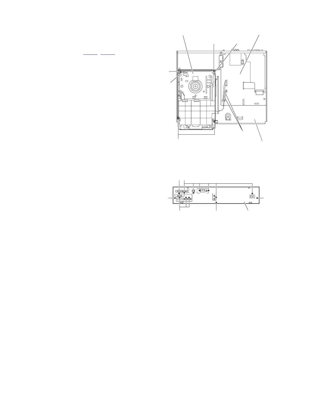
3.1.3 Removing the DVD changer mechanism assembly
(See Fig.7)
• Remove the metal cover.
• Remove the front panel assembly.
(1) From the top side of the main body, disconnect the card
wires from the connectors (CN405
, CN415) on the main
board.
(2) Remove the four screws D attaching the DVD changer
mechanism assembly to the bottom chassis.
(3) Take out the DVD changer mechanism assembly in an up-
ward direction.
Note:
When attaching the screw D, fit the hole of the DVD changer
mechanism assembly to the bosses d on the bottom chassis.
Fig.7
3.1.4 Removing the rear panel
(See Fig.8)
• Remove the metal cover.
(1) From the back side of the main body, remove the screw E,
nine screws F and three screws G attaching the rear panel.
Fig.8
Main board
Boss d
Boss d
CN405
CN415
Bottom chassis
DVD changer mechanism
assembly
Card wires
D
D
D
EF
F
GG
G
Rear panel
 Loading...