1-12 (No.MB067)
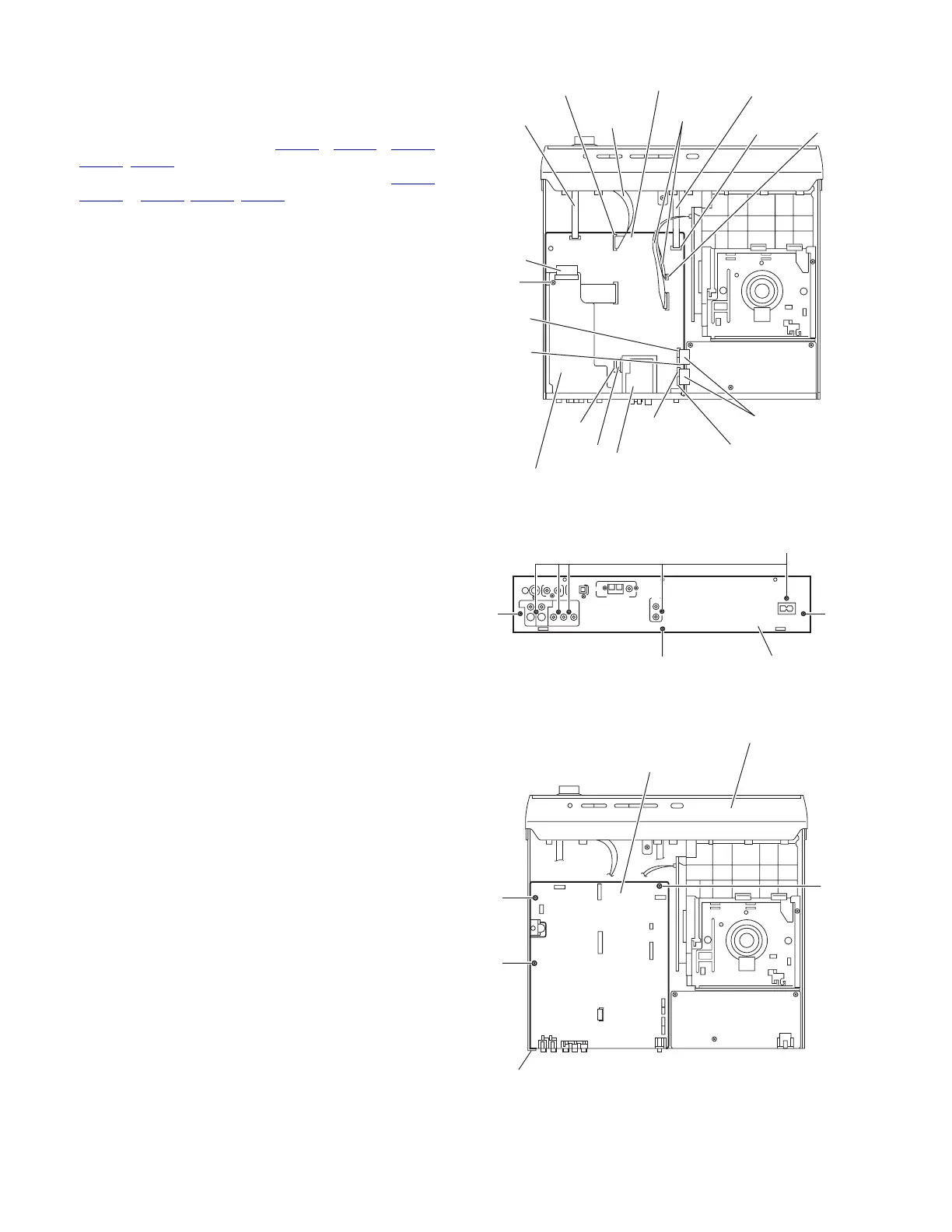
3.1.8 Removing the main board
(See Figs.11 to 13)
• Remove the metal cover.
(1) From the top side of the main body, disconnect the card
wires from the connectors (CN405, CN407, CN410,
CN411
, CN415) on the main board. (See Fig.11.)
(2) Disconnect the parallel wires from the connectors (CN416
,
CN402 to CN404, CN408, CN409) on the main board. (See
Fig.11.)
(3) Remove the screw P attaching the audio & digital input
board. (See Fig.11.)
(4) From the back side of the main body, remove the five
screws Q and three screws R attaching the rear panel.
(See Fig.12.)
(5) Take out the rear panel together the audio & digital input
board and tuner.
(6) From the top side of the main body, remove the three
screws S attaching the main board to the bottom chassis.
(See Fig.13.)
Fig.11
Fig.12
Fig.13
CN411
CN402
CN407
CN409
CN408
CN410
CN403
CN404
Tuner
Audio & Digital input board
Main board
P
CN416
CN405
CN415
Parallel wires
Card wire
Card wire
Card wire
Card wires
Parallel wire
Parallel wire
R
R
Q
Rear panel
Main board
S
S
S
Front panel assembly
Bottom chassis
 Loading...