1-16 (No.MB067)
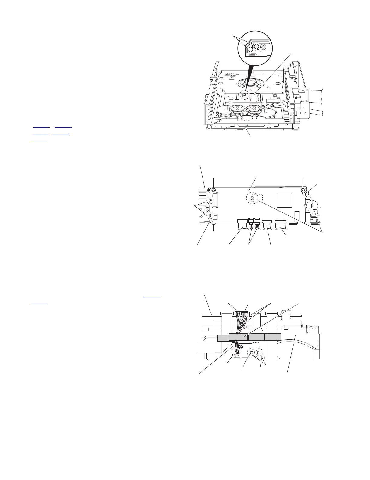
3.2.2 Removing the DVD servo board
(See Figs.6 and 7)
• Prior to performing the following procedures, remove the tray
assemblies.
(1) From the topside of the DVD changer mechanism assem-
bly, solder the short-circuit points d on the DVD pick up.
(See Fig.6.)
Caution:
Solder the short-circuit points d on the DVD pickup be-
fore disconnecting the flexible wire extending from the
DVD pickup. If you do not follow this instruction, the DVD
pickup may be damaged.
(2) From the right side of the DVD changer mechanism as-
sembly, disconnect the card wires from the connectors
(CN103
, CN201) and the wires from the connectors
(CN104
, CN205) and the flexible wire from the connector
CN101
on the DVD servo board. (See Fig.7.)
(3) Remove the screw B attaching the bracket to the DVD
changer mechanism assembly. (See Fig.7.)
(4) Release the two sections e of the bracket from the DVD
changer mechanism assembly and remove the DVD servo
board with the bracket. (See Fig.7.)
(5) Remove the two screws C attaching the DVD servo board
to the bracket. (See Fig.7.)
(6) Release the three sections f of the bracket and remove the
DVD servo board. (See Fig.7.)
Caution:
Unsolder the solders from the short-circuit points d after reas-
sembling.
Fig.6
Fig.7
3.2.3 Removing the switch board
(See Fig.8)
(1) From the bottom side of the DVD changer mechanism as-
sembly, disconnect the wires from connectors CN104
and
CN105
on the DVD servo board.
(2) Remove the screw D attaching the switch board to the DVD
changer mechanism assembly.
(3) Release the wires from the slots g of the switch board.
Caution:
When reassembling, let the wires through the slots g of the
switch board.
Reference:
When connecting the wires to the connectors on the DVD ser-
vo board, fix the wires with spacer.
Fig.8
DVD pickup
DVD changer mechanism assembly
Short circuit points d
DVD changer mechanism assembly
DVD servo board
Card wireBracket
Card wire
Wires Flexible wire
C
B
f
C
e
f
CN103 CN101
CN104
CN105
CN201
DVD servo board
CN104 CN105 Wires Spacer
Switch board
D
DVD changer
mechanism assembly
g
g
 Loading...