No.51961
TM-H1950CG
28
Item Test equipment Test points
Ad ju st men t
locations
Ad justment procedure
White
Balance
(High light)
93 00K
adjus tme nt
Signal generator
(Monoscope pattern)
C o lo ur t emp era t ur e
meter or Colour
An aly ser
W06 R DRIVE
W07 B DRIVE
[SERVICE MENU]
Finish the adjustment of low light completely first in
ad vanc e of th is ad ju stmen t.
1. Inp ut t he mon o-sc op e p atte rn signal .
2. Select th e WHI TE BALA NCE B LO CK mod e from
<BLOCK SE LECT> screen .
3. Se lect the 9 300 DRIV E adju stmen t mod e (High
lig ht 9300 mod e).
4. Ap ply the se nsor of th e colou r t empera tur e met er
to t he CRT surfac e, p ort ion of th e 10 0% whit e,
adjust the W06 (R DRIVE) or W07 (B DRIVE) to
setting 9300K (x=0.283, y=0.297).
5. Exit th e SE RVICE M ENU by pressin g t he “EX IT”
key.
6. Check th e whit e b alan ce tracking is fin est wh en
CONTRAST a nd BRIGHT are up an d down .
Br ight
adjus tme nt
Signal generator
(Sprit colour bar)
S01 (BRI GHT)
[SERVICE MENU]
Finish the adjustment of low light completely first in
ad vanc e of th is ad ju stmen t.
1. Inp ut a s pr it colour bar sig n al.
2. Select the SIGNAL BLOCK mode from <BLOCK
SE LECT> screen .
3. Se le ct t he S01 ite m.
4. Adjust th e S0 1 t o wh er e th e sp rit colo ur bar 0%
blac k comp one nt n ot t o br ig htens.
5. Check it t o on an d of f th e scr ee n displa y b y
tur n in g t he “DISP ” switch.
Contrast
adjus tme nt
Signal generator
(Full colour bar)
Oscillo-scope
TP-47G
TP-E( # )
[CRT SOCKET
PWB]
S02 (CONTRAST)
[SERVICE MENU]
1. Inp ut th e f ull colo ur b ar sign al. (7 5 / 0 / 75 / 0 set-
up level signal)
2.Connect the oscillo-scope probe to TP-47G and
TP-E(#).
3.Select the SIGNAL BLOCK mode from <BLOCK
SE LECT> screen .
4. Select t he S02 ite m.
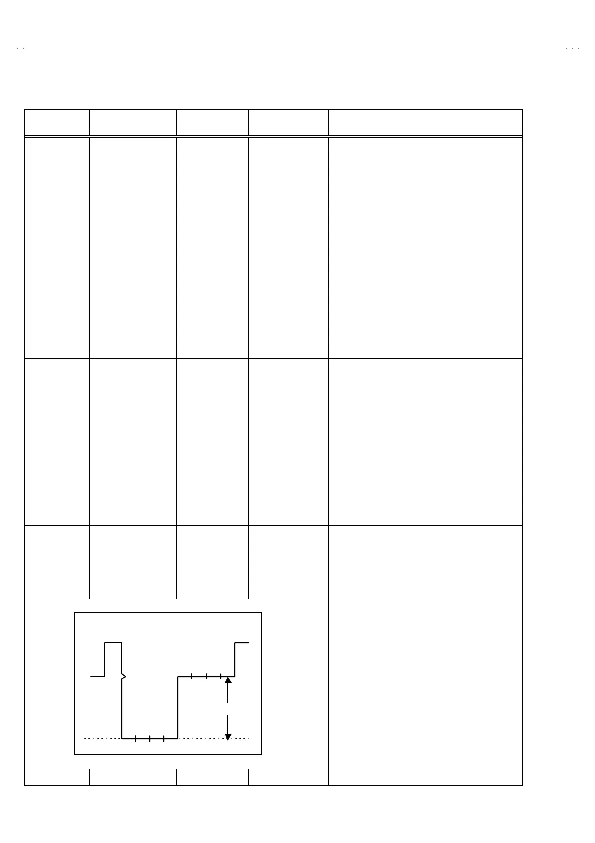
5. Adjust th e S0 2 t o b ecom e th e voltage diff er ent
b etween 7 5% wh it e a nd 0% black to
37 V±
±±
±2V p-p as sho wn in figur e.
V
75 -BL
=(37±
±±
± 2)V( p-p)
BLBRM
G
C
YW
75 %
WHITE

 Loading...