No.51961
TM-H1950CG
30
Item Test equipment Test points
Ad ju st men t
locations
Ad justment procedure
NT SC 3.5 8
PHASE
adjus tme nt
Signal generator
(Full colour bar)
Oscillo-scope
TP-47B
TP-E(#)
[CRT SOCKET
PWB]
S05 (NT SC PHASE)
[SERVICE MENU]
1. Input a NTSC 3.58 full colour bar signal.
2. Connect the oscillo-scope probe to TP-47B and
TP-E(#).
3. Sele ct t he SIGNAL BLOCK f rom SERVI CE
ME NU .
4. Select t he S05 item.
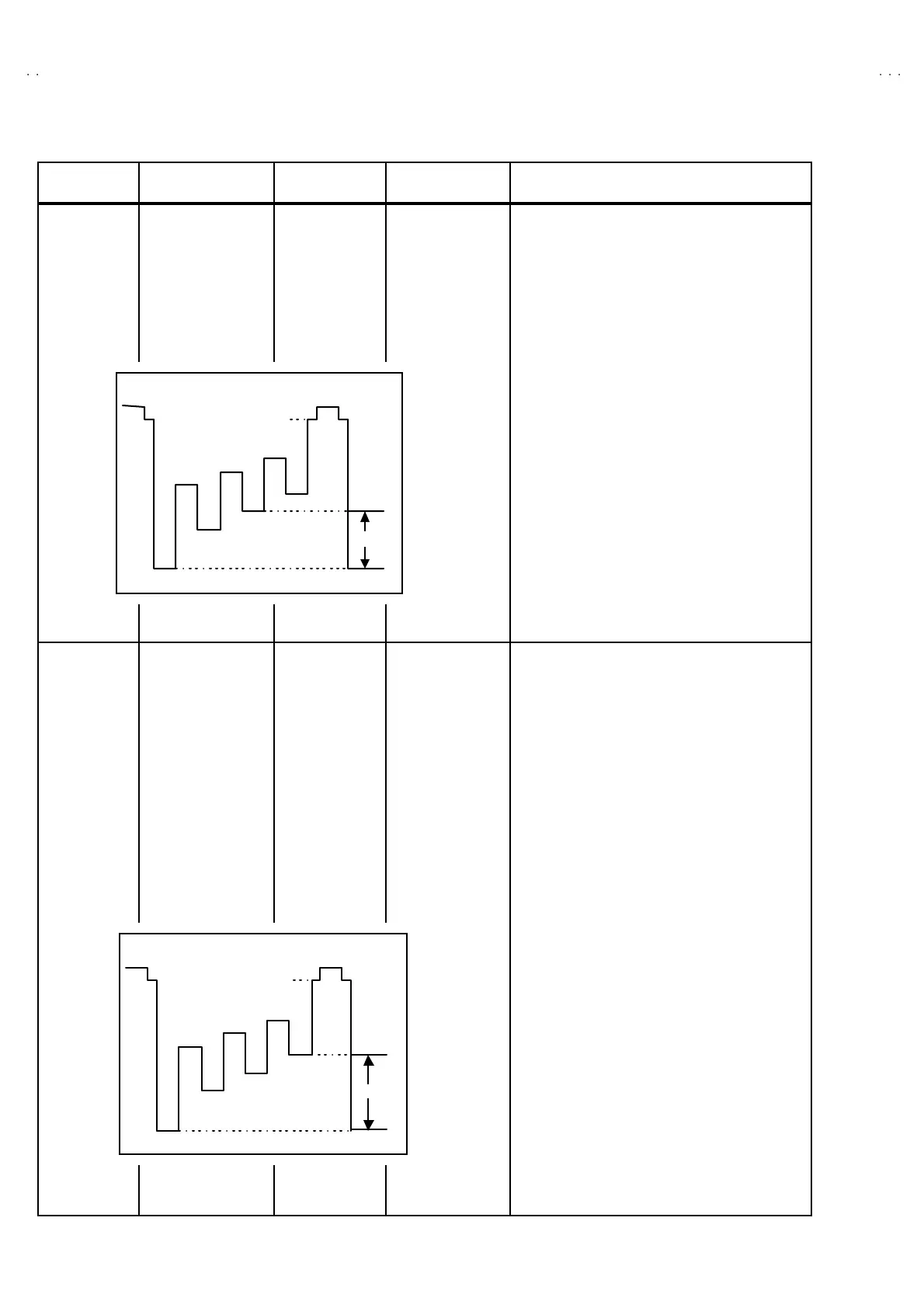
5. Adjust th e S0 5 to b ecom e t he v oltag e diff er en t
b etween 75 % wh it e and mage nta to 0V±2V p -p
as s hown in f igur e.
Component
signal
CHROMA
adjus tme nt
Component / RGB
input card
(IF-C01COM)
Signal generator
(Full colour bar)
Oscillo-scope
TP-47B
TP-E(#)
[CRT SOCKET
PWB]
S06 (NT SC PHASE)
[SERVICE MENU]
1. Turn off the main powe r s witch on th e rea r pa ne l.
2. Ins ert the com p onent / RGB inpu t card to th e rear
slot.
3. Input th e colour bar sign als (Y, B-Y, R-Y) t o each
ter mina l of t he c ompo ne nt / RGB inpu t card .
4. Se le ct t he “INPUT D” b y th e f ro nt pan el switch.
5. Connect the oscillo-scope probe to TP-47B and
TP-E(#).
6. Select t he SIGNAL B LOCK from SERVICE
ME NU .
7. Se le ct t he S0 6 ite m.
8. Ad ju st th e S0 6 t o b ecome t he volta ge diff eren t
between 75% white and blue to 0V ±
±±
±2V p-p as
sh own in figu re.
0V±
±±
±2V
BL
B
R
Mg
G
Cy
Y
W
75%
0V
±
±±
±
2V
BL
B
R
Mg
G
C
Y
W
75%

 Loading...