No.51961
TM-H1950CG
31
Item Test equipment Test points
Ad ju st men t
locations
Ad justment procedure
RGB signal
BR IG HT
adjus tme nt
Component / RGB
input card
(IF-C01COM)
Signal generator
(Sprit colour bar)
Signal distributor
S07 (RGB BRIGHT)
[SERVICE MENU]
1. Tur n off the main powe r s witch on th e rea r pane l.
2. Ins ert th e co mp on ent / RGB inpu t car d to t he r ear
slot.
3. Input the 3 kind signals (G:B :R, Y:Pb:Pr, Y:B-Y:R-
Y) to th e each t ermin al o f th e comp on ent / RGB
input card.
4. In c ase o f us in g t he c om posit e sync hron ous
sign al, in pu t t he s ynchron ous sign al t o the HD/CS
terminal only. B ut in c ase of using the separate
synch rono us sign al, inp ut th e ho rizo nta l
synch rono us signa l to the HD/ CS t ermin al and
vertical s yn chron ou s sign al to th e VD ter min al.
5. Se lect t he “INPUT D” by th e f ro nt pan el switch.
6. Se lect t he S IGNAL BLO CK from SERVI CE MENU.
7. Se lect t he S07 ite m.
8. Ad ju st the S0 7 to where t he sprit c olou r bar 0 %
blac k comp one nt not to bright ens .
9. Check it out b y pre ssing th e “DISP ” switch o n an d
off .
RGB signal
CONT RAST
adjus tme nt
Component / RGB
input card
(IF-C01COM)
Signal generator
(Sprit colour bar)
Signal distributor
Oscillo-scope
TP-47G
TP-E(#)
[CRT SOCKET
PWB]
S08 (RGB
CONT RAST)
[SERVICE MENU]
1. Tur n off the main powe r s witch on th e rea r pane l.
2. Ins ert th e co mp on ent / RGB inpu t car d to t he r ear
slot.
3. Input the 3 kind signals (G:B :R, Y:Pb:Pr, Y:B-Y:R-
Y) to th e each t ermin al o f th e comp on ent / RGB
input card.
4. In c ase o f us in g t he c om posit e sync hron ous
sign al, in pu t t he s ynchron ous sign al t o the HD/CS
terminal only. B ut in c ase of using the separate
synch rono us sign al, inp ut th e ho rizo nta l
synch rono us signa l to the HD/ CS t ermin al and
vertical s yn chron ou s sign al to th e VD ter min al.
5. Se lect t he “INPUT D” by th e f ro nt pan el switch.
6. Connect the oscillo-scope probe to TP-47G and
TP-E(#).
7. Se lect t he S IGNAL BLO CK from SERVI CE MENU.
8. Se lect t he S08 ite m.
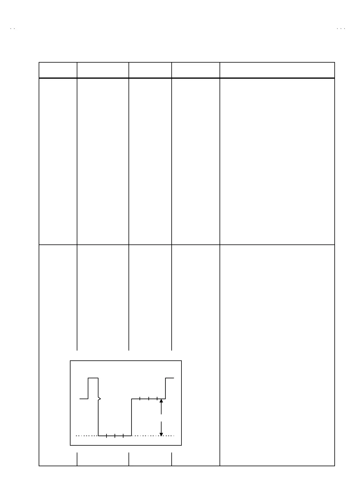
9. Ad just th e S0 8 t o become t he volta ge diff er ent
between 75% white and blue to 37 V±
±±
± 2Vp-p as
sh own in figu re.
V
75 -BL
=(37±
±±
± 2)V( p-p)
BLBRM
GCyYW
75 %
WHITE

 Loading...