No. 51961
TM-H1950CG
38
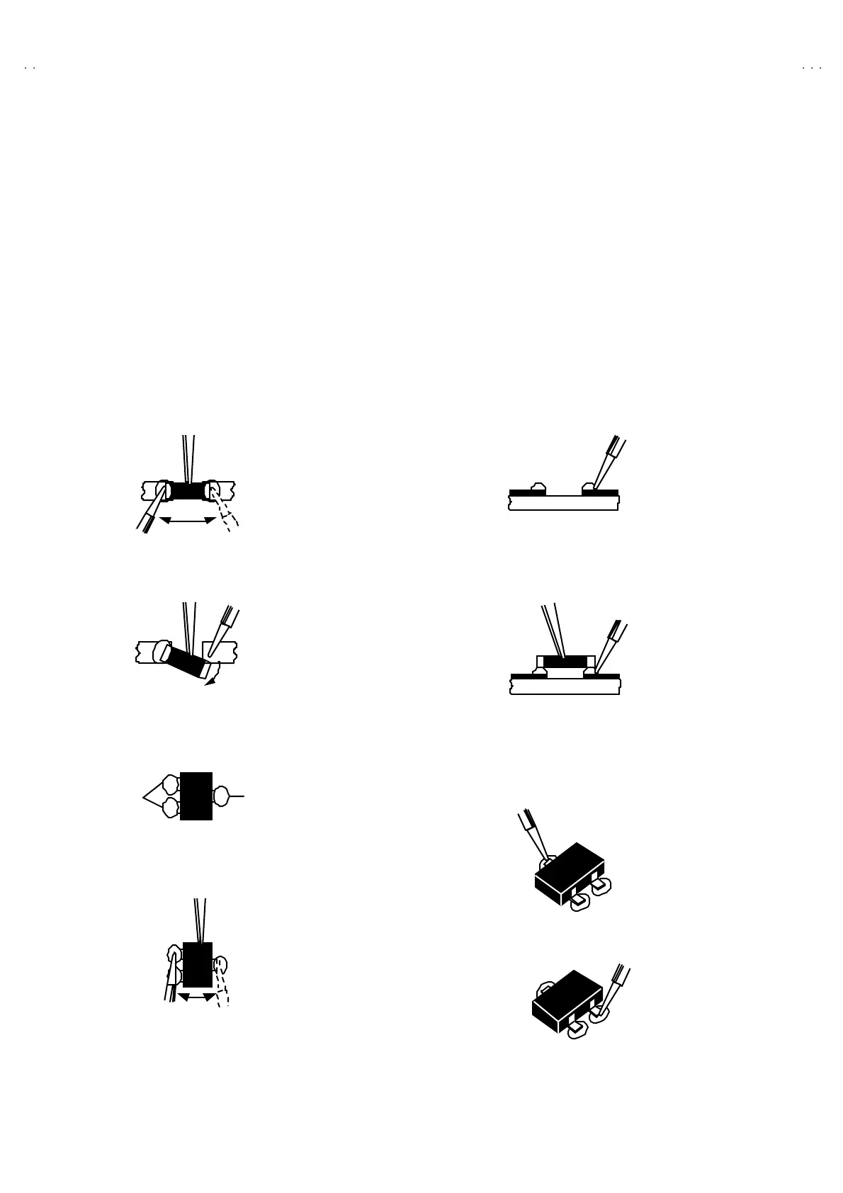
REPLACE OF THE CHIP COMPONENT
CAUTIONS
1. Avoid heating for more than 3 seconds.
2. Do n ot rub t he elect ro des and t he resist p arts of th e patt er n.
3. When r emoving a c hip part, melt the s older adequ ate ly.
4. Do n ot reuse a ch ip p ar t afte r re mo ving it .
SOLDERING IRON
1. Use a hig h ins ulatio n s oldering iron with a t hin po in ted e nd of it .
2. A 3 0 w s oldering ir on is rec omm ended for easily r emoving p arts.
REPLACEMENT STEPS
1. How to remove Chip parts
Resi st ors, ca pa citors , etc .
(1) As sho wn in th e figur e, p ush th e pa rt with twee zer s a nd
alte rn at ely melt the solde r at each en d.
(2) Shif t with tweeze rs and remo ve th e ch ip p art.
Trans ist ors, diodes , va ria bl e r es ist or s, etc.
(1) Ap ply e xt ra so ld er to ea ch le ad .
(2) As sho wn in th e figur e, p ush th e pa rt with twee zer s a nd
alte rn at ely melt the sold er at e ach le ad . Shift and rem ove
the chip p art .
Note : After removing the part, remove remaining solder from
the pattern.
2. How to install Chip parts
Resi st ors, ca pa citors , etc .
(1) Apply sold er to the pattern as indic ated in the figure.
(2) Grasp th e ch ip p art wit h t weez ers and p lace it on th e
sold er. Th en h eat and me lt the solder at b oth e nds of the
chip part.
Trans ist ors, diodes , va ria bl e r es ist or s, etc.
(1) Apply sold er to the pattern as indic ated in the figure.
(2) Grasp th e ch ip p art wit h t weez ers and p lace it on th e
solder.
(3) First solder lead
A
as indica ted in the figure.
(4) The n so ld er le ads B and C.
SOLDE R
SOLDE R
A
B
C
A
B
C

 Loading...