(No.MB286)1-13
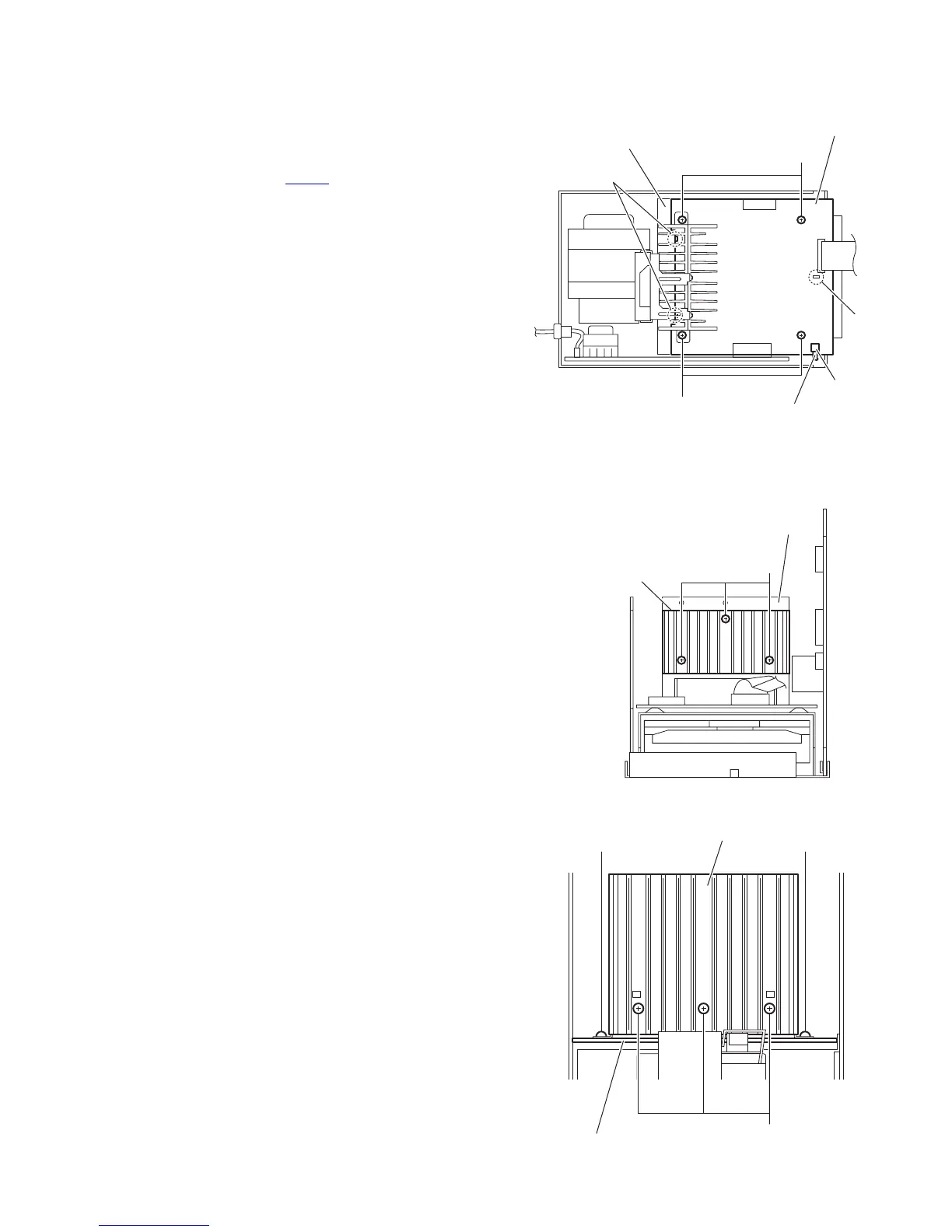
3.1.12 Removing the power amplifier board
(See Fig.19)
• Prior to performing the following procedures, remove the side
panels L/R, front panel assembly, top cover assembly, rear
panel, tuner, video board, main board and power supply board.
(1) From the top side of the main body, disconnect the card
wire from the connector CN404
on the power amplifier
board.
(2) Remove the four screws N attaching the power amplifier
board.
(3) Lift the power amplifier board and remove it from the en-
gagement sections (h, i) of the shield case.
Fig.19
3.1.13 Removing the heat sink B and heat sink
(See Figs.20 and 21)
• Prior to performing the following procedure, remove the side
panels L/R, front panel assembly, top cover assembly, rear
panel and fan.
(1) From the front side of the main body, remove the three
screws P attaching the heat sink B to the heat sink. (See
Fig.20.)
(2) From the back side of the main body, remove the three
screws Q attaching the heat sink to the power amplifier
board. (See Fig.21.)
(3) From the top side of the main body, remove the two screws
R attaching the heat sink to the power amplifier board. (See
Fig.21.)
Reference:
Remove the tuner and video board as required.(See Figs.14
and 15.)
Fig.20
Fig.21
Power amplifier board
CN404
i
h
N
N
Shield case
Card wire
P
Heat sink B
Heat sink
Heat sink
Power amplifier board
Q
R R

 Loading...


