(No.MB286)1-17
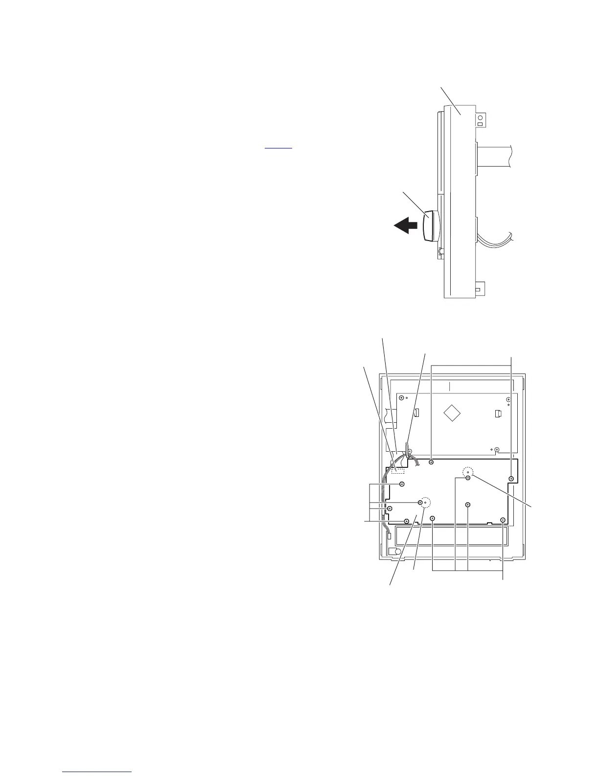
3.1.17 Removing the switch board
(See Figs.27 and 28)
• Prior to performing the following procedures, remove the side
panels L/R and front panel assembly.
(1) From the front side of the front panel assembly, pull out the
volume knob in to the direction of the arrow. (See Fig.27.)
(2) From the inside of the front panel assembly, remove the
ten screws W attaching the switch board. (See Fig.28.)
(3) Take out the switch board from the front panel assembly
and disconnect the card wire from the connector CN760
on
the switch board. (See Fig.28.)
Reference:
• When removing the switch board, remove the wire holder as
required. (See Fig.26.)
• When attaching the switch board, align the projections q of
the front panel assembly in the holes of the switch board.
(See Fig.28.)
Fig.27
Fig.28
Microphone
volume knob
Front panel assembly
CN760
Card wire
W
q
q
W
W
Switch board
Wire holder

 Loading...


