EasyManua.ls Logo

JVC XP-A1000BK - Page 20

JVC XP-A1000BK
73 pages
Print Icon
To Next Page IconTo Next Page
To Previous Page IconTo Previous Page
Loading...
XP-A1000BK
DISTRIBUTION
PATTERN
OF
VIRTUAL
IMAGE
SOURCE
LOCATIONS
IN
A
“LIVE”
LISTENING
ROOM
Left
U
O
©)
a
e
o
&
DO)
£9
aay
er
a
S
Oxy
Ww
USE
Fig.
3b
Right
The
Sound
Field
in
the
Recording
Source
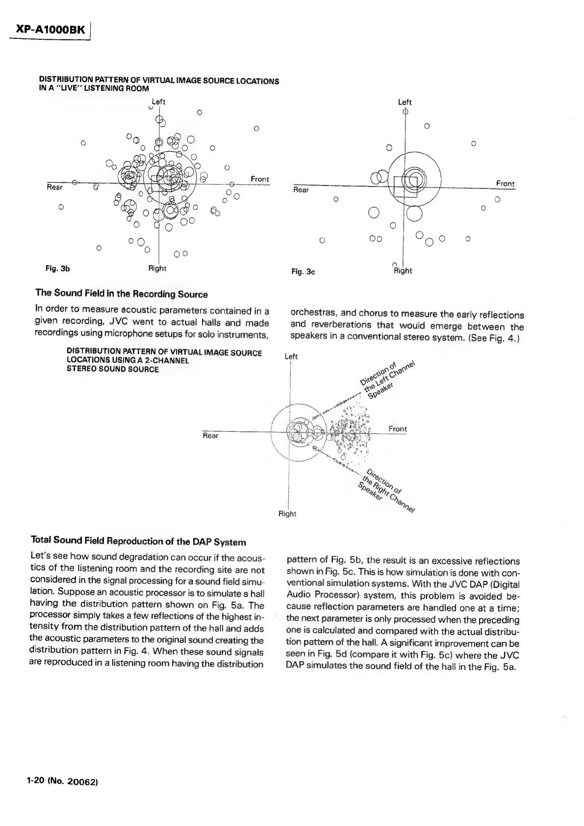
In
order
to
measure
acoustic
parameters
contained
in
a
given
recording,
JVC
went
to
actual
halls
and
made
recordings
using
microphone
setups
for
solo
instruments,
DISTRIBUTION
PATTERN
OF
VIRTUAL
IMAGE
SOURCE
LOCATIONS
USING
A
2-CHANNEL
STEREO
SOUND
SOURCE
Rear
Fig.
3c
orchestras,
and
chorus
to
measure
the
early
reflections
and
reverberations
that
would
emerge
between
the
speakers
in
a
conventional
stereo
system.
(See
Fig.
4.)
Left
!
Rear
Total
Sound
Field
Reproduction
of
the
DAP
System
Let’s
see
how
sound
degradation
can
occur
if
the
acous-
tics
of
the
listening
room
and
the
recording
site
are
not
considered
in
the
signal
processing
for
a
sound
field
simu-
lation.
Suppose
an
acoustic
processor
is
to
simulate
a
hall
having
the
distribution
pattern
shown
on
Fig.
5a.
The
processor
simply
takes
a
few
reflections
of
the
highest
in-
tensity
from
the
distribution
pattern
of
the
hall
and
adds
the
acoustic
parameters
to
the
original
sound
creating
the
distribution
pattern
in
Fig.
4.
When
these
sound
signals
are
reproduced
in
a
listening
room
having
the
distribution
1-20
(No.
20062)
pattern
of
Fig.
5b,
the
result
is
an
excessive
reflections
shown
in
Fig.
5c.
This
is
how
simulation
is
done
with
con-
ventional
simulation
systems.
With
the
JVC
DAP
(Digital
Audio
Processor)
system,
this
problem
is
avoided
be-
cause
reflection
parameters
are
handled
one
at
a
time;
the
next
parameter
is
only
processed
when
the
preceding
one
is
calculated
and
compared
with
the
actual
distribu-
tion
pattern
of
the
hall.
A
significant
improvement
can
be
seen
in
Fig.
5d
(compare
it
with
Fig.
5c)
where
the
JVC
DAP
simulates
the
sound
field
of
the
hall
in
the
Fig.
5a.