EasyManua.ls Logo

JVC XP-A1000BK - Removal Procedures

JVC XP-A1000BK
73 pages
Print Icon
To Next Page IconTo Next Page
To Previous Page IconTo Previous Page
Loading...
XP-A1000BK
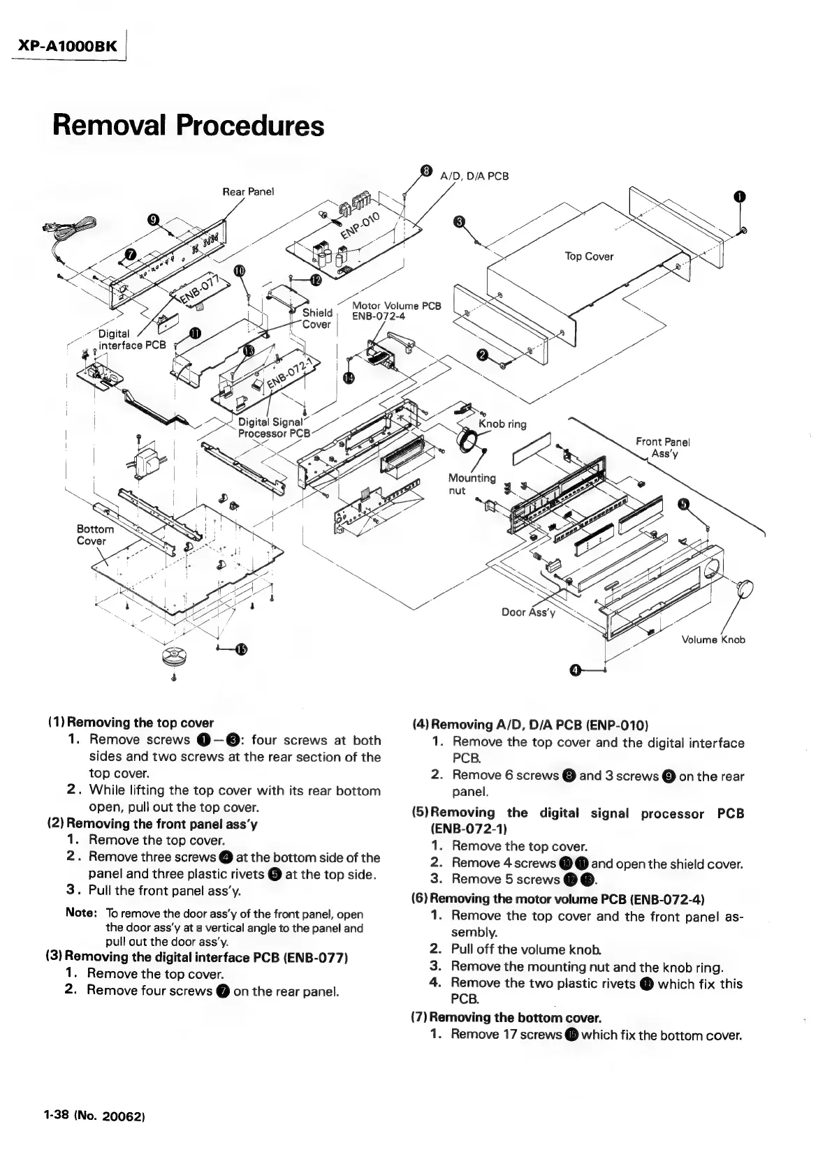
Removal
Procedures
Rear
Panel
Pa
>
Digital
‘6
Ps
;interface
PCB
Digital
Signal~
ee.
Processor
PCB
Foe
~
4
she
‘
LS
me
=
%
*
(1)
Removing
the
top
cover
1.
Remove
screws
@—®:
four
screws
at
both
sides
and
two
screws
at
the
rear
section
of
the
top
cover.
2.
While
lifting
the
top
cover
with
its
rear
bottom
open,
pull
out
the
top
cover.
(2)
Removing
the
front
panel
ass’y
1.
Remove
the
top
cover.
2.
Remove
three
screws
@
at
the
bottom
side
of
the
panel
and
three
plastic
rivets
@
at
the
top
side.
3.
Pull
the
front
panel
ass’y.
Note:
To
remove
the
door
ass’y
of
the
front
panel,
open
the
door
ass’y
at
a
vertical
angle
to
the
panel
and
pull
out
the
door
ass’y.
(3)
Removing
the
digital
interface
PCB
(ENB-077)
1.
Remove
the
top
cover.
2.
Remove
four
screws
@
on
the
rear
panel.
1-38
(No.
20062)
vate
Volume
PCB
ENB-072-4
SZ
4
Mounting
A/D,
D/A
PCB
ee
ae
iS
Knob
ring
Sa)
Front
Panel
nut
3°
(4)
Removing
A/D,
D/A
PCB
(ENP-010)
1.
Remove
the
top
cover
and
the
digital
interface
PCB.
2.
Remove
6
screws
@
and
3
screws
@
on
the
rear
panel.
(5)Removing
the
digital
signal
processor
PCB
(ENB-07
2-1)
1.
Remove
the
top
cover.
2.
Remove
4
screws
@@
and
open
the
shield
cover.
3.
Remove
5
screws
@@.
(6)
Removing
the
motor
volume
PCB
(ENB-072-4)
1.
Remove
the
top
cover
and
the
front
panel
as-
sembly.
2.
Pull
off
the
volume
knob.
3.
Remove
the
mounting
nut
and
the
knob
ring.
4.
Remove
the
two
plastic
rivets
@
which
fix
this
PCB.
(7)
Removing
the
bottom
cover.
1.
Remove
17
screws
@
which
fix
the
bottom
cover.