EasyManua.ls Logo

JVC XP-A1000BK - Adjustment Procedures

JVC XP-A1000BK
73 pages
Print Icon
To Next Page IconTo Next Page
To Previous Page IconTo Previous Page
Loading...
XP-A1000BK
Adjustment
Procedures
@
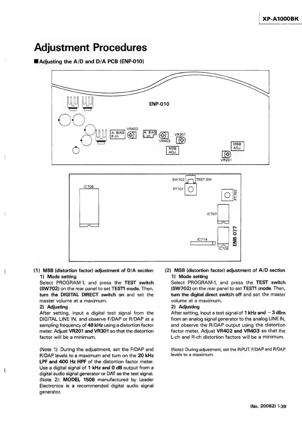
Adjusting
the
A/D
and
D/A
PCB
(ENP-010)
we
Se
©
(1)
MSB
(distortion
factor)
adjustment
of
D/A
section
1)
Mode
setting
Select
PROGRAM-1,
and
press
the
TEST
switch
(SW702)
on
the
rear
panel
to
set
TEST1
mode.
Then,
turn
the
DIGITAL
DIRECT
switch
on
and
set
the
master
volume
at
a
maximum.
2)
Adjusting
After
setting,
input
a
digital
test
signal
from
the
DIGITAL
LINE
IN,
and
observe
F/DAP
or
R/DAP
at
a
sampling
frequency
of
48
kHz
using
a
distortion
factor
meter.
Adjust
VR201
and
VR301
so
that
the
distortion
factor
will
be
a
minimum.
(Note
1):
During
the
adjustment,
set
the
F/DAP
and
R/DAP
levels
to
a
maximum
and
turn
on
the
20
kHz
LPF
and
400
Hz
HPF
of
the
distortion
factor
meter.
Use
a
digital
signal
of
1
kHz
and
O
dB
output
from
a
digital
audio
signal
generator
or
DAT
as
the
test
signal.
(Note
2):
MODEL
1506
manufactured
by
Leader
Electronics
is
a
recommended
digital
audio
signal
generator.
ENP-010
{)
VR402
UL
vagon
C)
Sry
ADJ.
ADJ.
[(@)
Sw702
fel
TEST
SW
(2)
MSB
(distortion
factor)
adjustment
of
A/D
section
1)
Mode
setting
Select
PROGRAM-1,
and
press
the
TEST
switch
(SW702)
on
the
rear
panel
to
set
TEST1
mode.
Then,
turn
the
digital
direct
switch
off
and
set
the
master
volume
at
a
maximum.
2)
Adjusting
After
setting,
input
a
test
signal
of
1kHz
and
—3
dBm
from
an
analog
signal
generator
to
the
analog
LINE
IN,
and
observe
the
R/DAP
output
using
the
distortion
factor
meter.
Adjust
VR402
and
VR403
so
that
the
L-ch
and
R-ch
distortion
factors
will
be
a
minimum.
(Note):
During
adjustment,
set
the
INPUT,
F/DAP
and
R/DAP
levels
to
a
maximum.
(No.
20062)
1-39