EasyManua.ls Logo

JVC XP-A1000BK - Page 31

JVC XP-A1000BK
73 pages
Print Icon
To Next Page IconTo Next Page
To Previous Page IconTo Previous Page
Loading...
XP-A1000BK
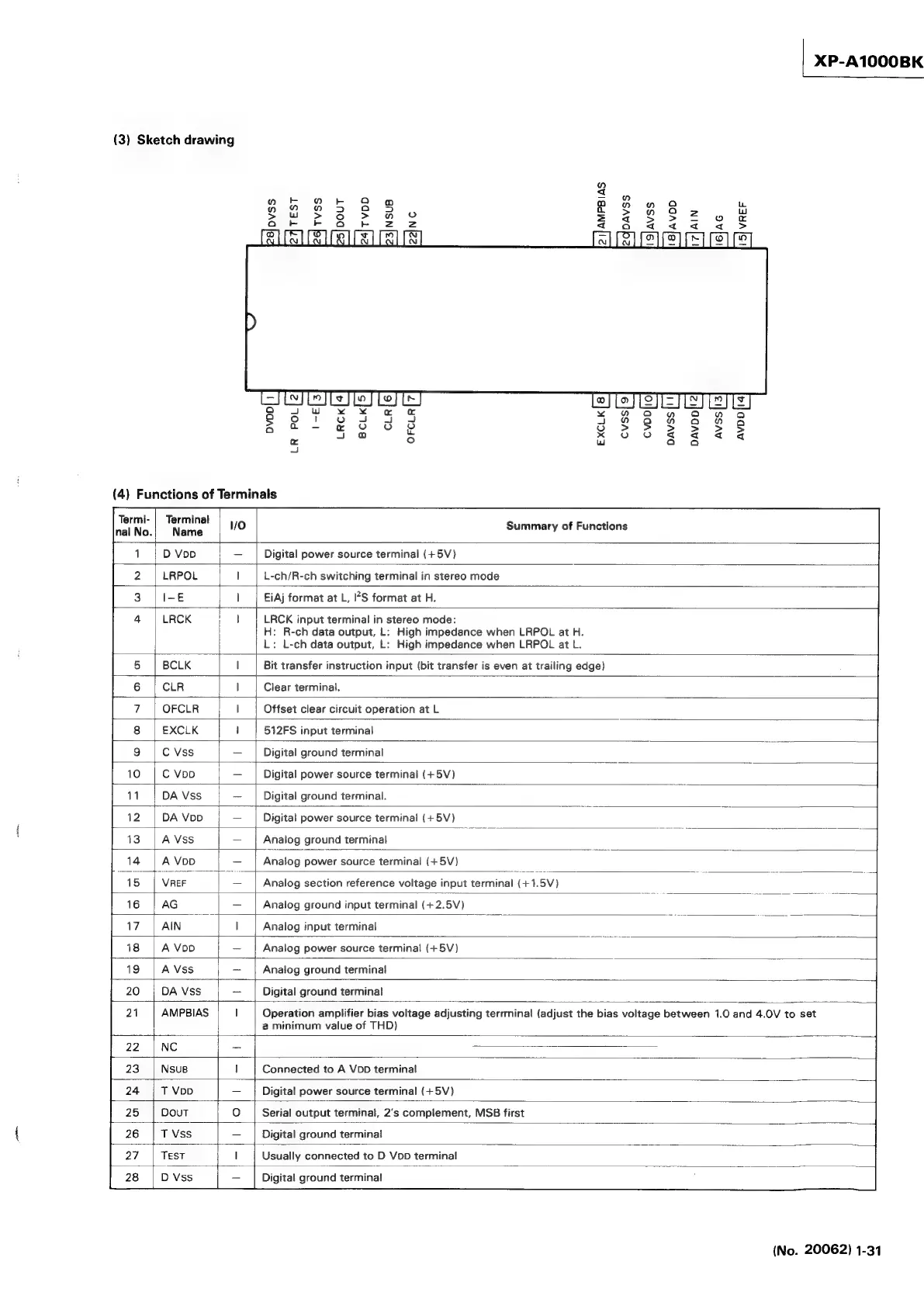
(3)
Sketch
drawing
TEST
Tvss
DOUT
NSUB
NC
AMPBIAS
DAVSS
AIN
AG
VREF
24]
voD
21]
i
g|avss
i
8]avoo
“a
n
>
a
Ea
JIstests
jie]
Ley
Te
Lo}
[>]
[2
]]
=|
LS
|
x
¥~¥
YW
OO
WwW
AH
QO
{2}
4
_
a
ee
gS
e888
m
2
°
Ww
a
4
ie
(4)
Functions
of
Terminals
Terminal
Summary
of
Functions
Digital
power
source
terminal
(+5V)
L-ch/R-ch
switching
terminal
in
stereo
mode
EiAj
format
at
L,
’S
format
at
H.
LRCK
input
terminal
in
stereo
mode:
H:
R-ch
data
output,
L:
High
impedance
when
LRPOL
at
H.
L:
L-ch
data
output,
L:
High
impedance
when
LRPOL
at
L.
Bit
transfer
instruction
input
(bit
transfer
is
even
at
trailing
edge)
Clear
terminal.
Offset
clear
circuit
operation
at
L
512FS
input
terminal
Digital
ground
terminal
Digital
power
source
terminal
(+5V)
Digital
ground
terminal.
Digital
power
source
terminal
(+5V)
Analog
ground
terminal
Analog
power
source
terminal
(+
5V)
Analog
section
reference
voltage
input
terminal
(+1.5V)
Analog
ground
input
terminal
(+2.5V)
Analog
input
terminal
A
VoD
Analog
power
source
terminal
(+5V)
A
Vss
Analog
ground
terminal
DA
Vss
Digital
ground
terminal
AMPBIAS
Operation
amplifier
bias
voltage
adjusting
terrminal
(adjust
the
bias
voltage
between
1.0
and
4.0V
to
set
a
minimum
value
of
THD)
NC
Connected
to
A
VDD
terminal
Digital
power
source
terminal
(+5V)
Serial
output
terminal,
2's
complement,
MSB
first
Digital
ground
terminal
Usually
connected
to
D
VoD
terminal
Digital
ground
terminal
(No.
20062)
1-31