EasyManua.ls Logo

JVC XP-A1000BK - Page 54

JVC XP-A1000BK
73 pages
Print Icon
To Next Page IconTo Next Page
To Previous Page IconTo Previous Page
Loading...
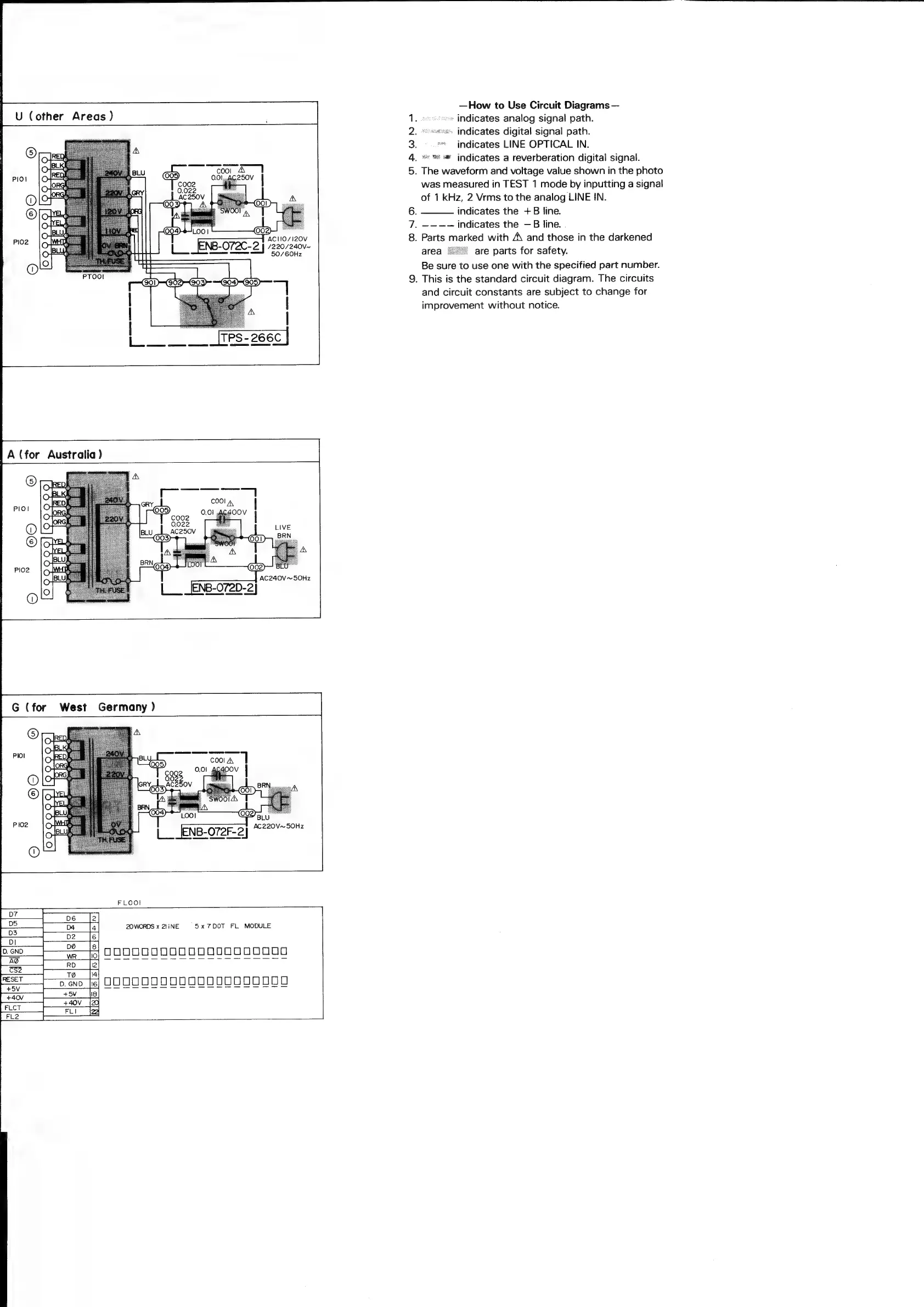
U
(other
Areas)
‘AC
110/120
ENB-O72C-2
|
/220/240v~
50/60Hz
A
(for
Australia)
PI02
AC240V~50Hz
i
COO!
A,
P102
AC220V~50Hz
NB-O72F-2]
FLOOI
or
6
Te
2OWORDS
x
21iNE
=
5x
7DOT
FL
MODULE
|
2
sd
|
ee
fond}
—22@
{84
OOOOOCOOOOOO00000000
|
RD
OND
aARWN>
—How
to
Use
Circuit
Diagrams
—
»
indicates
analog
signal
path.
«.
indicates
digital
signal
path.
»*
indicates
LINE
OPTICAL
IN.
ws
a
indicates
a
reverberation
digital
signal.
.
The
waveform
and
voltage
value
shown
in
the
photo
was
measured
in
TEST
1
mode
by
inputting
a
signal
of
1
kHz,
2
Vrms
to
the
analog
LINE
IN.
indicates
the
+B
line.
.
~-—-—-—
indicates
the
—B
line.
.
.
Parts
marked
with
A\
and
those
in
the
darkened
are
parts
for
safety.
Be
sure
to
use
one
with
the
specified
part
number.
.
This
is
the
standard
circuit
diagram.
The
circuits
and
circuit
constants
are
subject
to
change
for
improvement
without
notice.