Technical Manual Construction and function
1304045088 - 11/2016Kaba wireless gateway 90 40
4 Construction and function
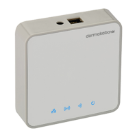
4.1 Device construction
Front Back
1 Power supply input
2 Ethernet Interface
3 Range measurement button (not visible)
4 LED status display
5 USB interface (Type A)
6 Reset button
4.2 LEDs
4.2.1 Status indicators
The wireless gateway is equipped with four LED status indicators on the front.
Boot process
The boot process phases are indicated by the status LEDs.
The right column indicates the start of the various phases.
LED Status Phase After approx.
On Boot loader is starting 0s
Off Kernel is loading 10s
Flashes 2x Operating system is starting 20s
Flashes 1x Operating system is running
Application is starting
40s
On (30s)
Off (1s)
Application is running
Boot process is complete
4 min
Reset
The triggering of a reset is signalled by the status LEDs.
LED Status Phase
Flickers Reset triggered
Flashes 2x Kernel is shutting down
On Boot loader is starting
Start of boot process, see above