Installation Technical Manual
16 04045088 - 11/2016 Kaba wireless gateway 90 40
5.1.3 Connections
The following connections must be prepared at the installation location:
• Ethernet network connection
• Power supply for the wireless gateway (only if PoE not available)
If there is no PoE network switch available in compliance with IEEE standard 802.3af,
a PoE injector can be used to provide a data and power connection for the device.
Alternatively, the wireless gateway can be provided with data via the network con-
nection, and then powered via a separate cable running to the external power sup-
ply [}3.2.3].
5.2 Installation diagram
Wireless device
Wireless communication
1 Host system
2 PoE network switch or PoE injector and network switch (IEEE 802.3af)
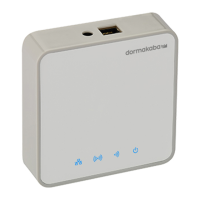
3 Wireless gateway
4 External power supply (optional)
5 Wireless component
Installation cables
A Ethernet network cable
B Power supply cable (optional)