Section 3 - 17
Key Cutting & Pinning
Comparing A2 Pin Stacks
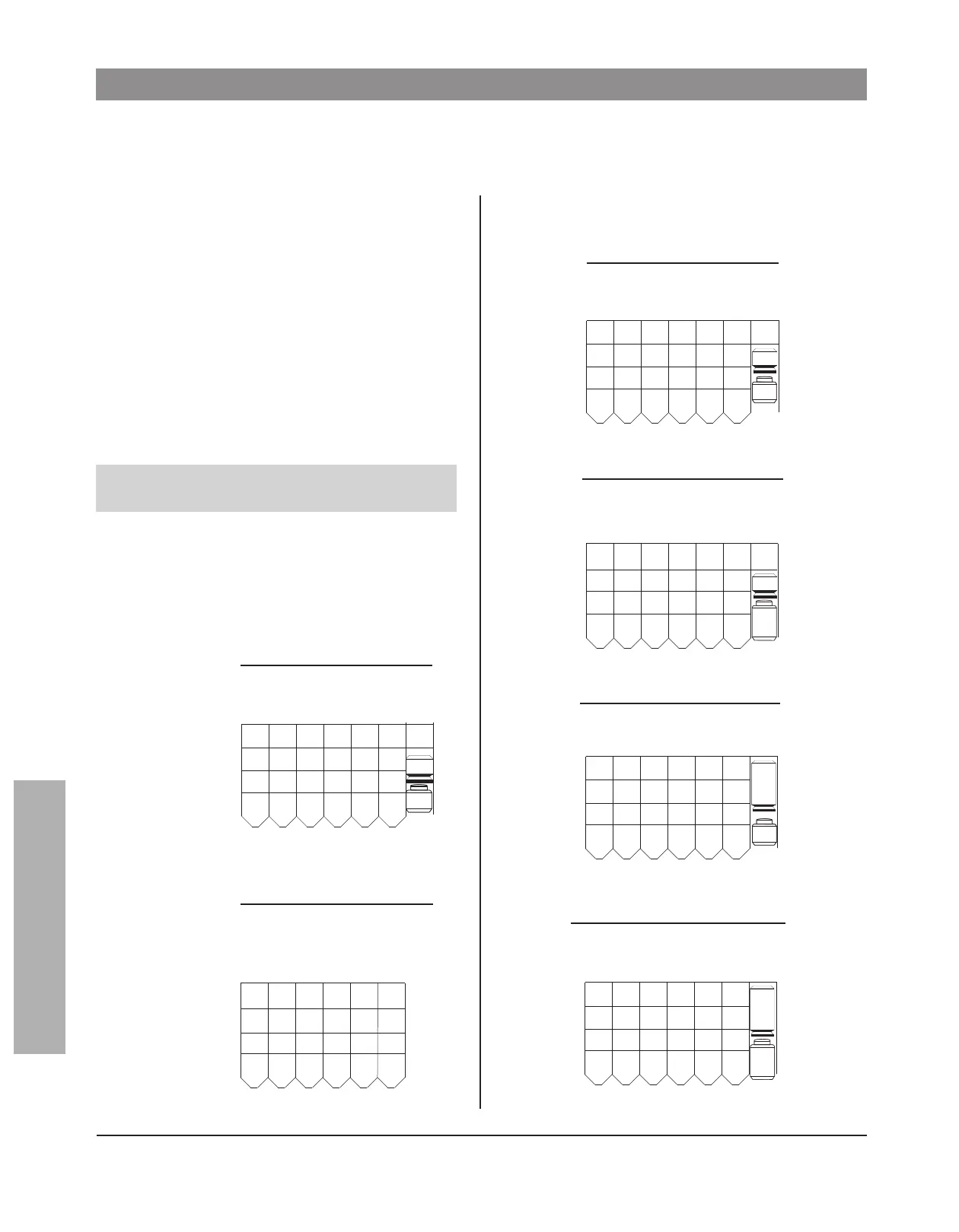
The examples on this page show pinning for key
symbol 1AA.
W
hen pinning conventional cylinders, ignore the con-
trol bitting. If a top pin of 20 or greater is needed,
use two pins of equal length to bring the pin stack to
the required height. When an odd numbered top pin
is required, such as 21, use two pins that are close
in size—11 and 10 instead of 13 and 8.
For the patent pin chamber in all conventional cylin-
ders, insert the proper bottom and top patent pins,
then insert a number 7B top pin.
Pinning for all Peaks products can now be accom-
plished with only one spring. That stainless steel
spring is number 3800-00-4010.
Note: Peaks Preferred Patent Pins for illustration
only. (See key pinning section 3 - 4 to 3 - 12)
Stack height 26
control CTR 779631
master AA 951473
change 1AA 593875
top 17 17 12 18 19 11
buildup 11 10
master 4424- 2
bottom 551473
7B
8400-xx-1206
3400-xx-1206
Key-in-Knob
8401-xx-1210
3401-xx-1210
Rim/Mortise
top 11 11 14 12 12 13
buildup 11 11 14 11 12 13
master 4424- 2
bottom 551473
7B
8800/8900
3800/6800
Small Format
Interchangeable Core
top 664710 12
control 8816 866
master 4424- 2
bottom 551473
Stack height 31
Stack height 23
8400-xx-1299
3400-xx-1299
"99" and "95" Key-in-Knob
top 17 17 12 18 19 11
buildup --11 --10
master 4424- 2
bottom 551473
7B
8244-xx-1206 Yale
6240-xx-1206 Yale
6340-xx-1206 Medeco
top 99710 13 15
control 8816 866
master 4424- 2
bottom 551473
8144-xx-1206
6140-xx-1206
Corbin Russwin
top 99710 13 15
control 8816 866
master 4424- 2
bottom 551473
Calculating Other A2 Pinning Stacks
 Loading...