#4 top pin makes stack total 23.
#12 buildup pin makes stack
height 19 for control.
#2 master pin makes #7 cut
of change key work.
#5 bottom pin for #5 cut of TMK
change key cut is 7
Section 3 - 18
Key Cutting & Pinning
4
12
2
5
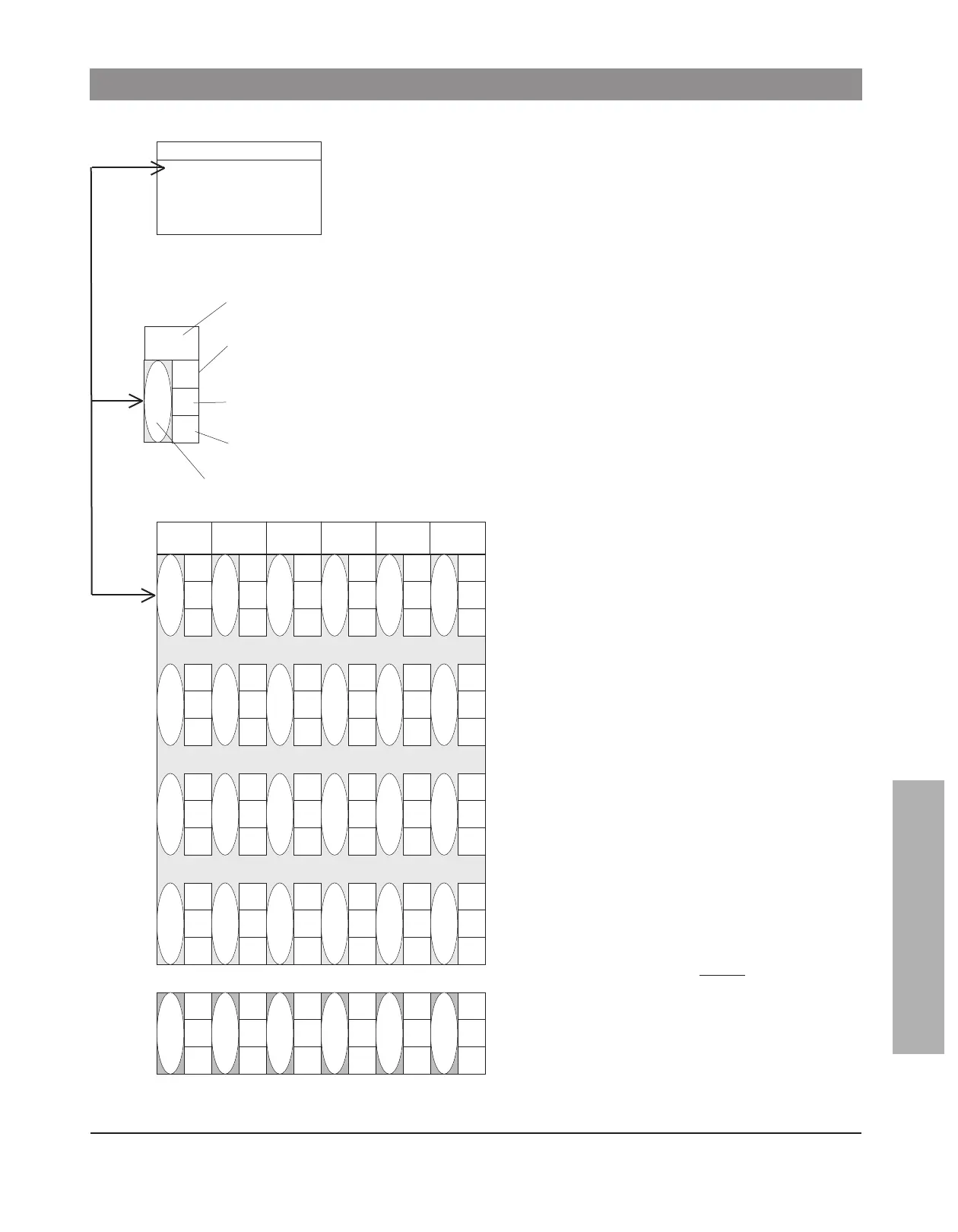
A small format interchangeable core pinning chart is an expanded
k
ey bitting array (KBA) that speeds pinning. At the left is a key bit-
ting array. The control combination is a change key that is set aside.
S
OP stands for Sequence of Progression.
7
The inset at the left shows the pin stack for
the first change key possibility in the first
chamber.
The “7” from the KBA is in the large oval.
To the right of the oval are the pins needed
to make the #7 cut work with the #5 cut of
the top master key and the #9 cut of the
control key. Pin stacks are read from the
bottom up.
The complete pinning chart contains every
possible pin stack for every possible
change key and master key in the system.
To pin a core to a given key, find the bitting
of the key in each position in the large oval
and install the pins indicated in the squares
next to the oval.
The bottom row beneath the heading
“complete pin stacks for constants”, gives
complete pin stacks, including top pins, for
the rotating constant method, or for pinning
to master keys only.
Factory bitting lists come with pinning
charts. To make a pinning chart, fill in the
large ovals with the cuts in the key bitting
array, and do the pin stack calculations one
column at a time.
SKD’s and cross keying
SKD’s and cross keying cannot
be pinned
from this chart. SKD’s are never master
keyed. Cross keying must be calculated
separately for each keying specification.
top
pins
complete pin stacks for constants
4713 965
12 12 2614 12
226222
522614
14 14 2812 14
224642
304012
14 828814
462484
126210
10 10 2810 10
448264
520414
4713 965
14 14 2816 14
528614
742836
304052
186290
960478
528614
Control 960478
T
MK 528614
742836
3
04052
186290
960478
SOP abcde f
A2 System Small Format Interchangeable Core Pinning Charts

 Loading...