Page 14 Installation Instructions Powador 1501xi/2501xi*/3501xi/4501xi/5001xi**_EN
To connect the inverter, the AC and DC sides must be discon-
nected from all power sources and secured against being inad-
vertently switched back on. The connection of the PV generator
and the grid connection are established via PCB terminals in
the inverter’s connection box (see fi gures 6.3 and 6.4).
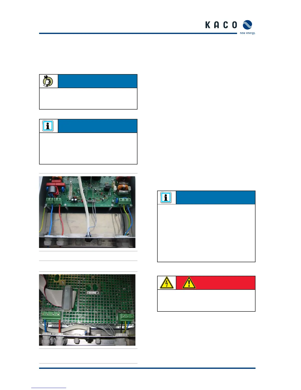
Figure 6.3: Powador 1501xi connection box
Figure 6.4: Connection box of the Powador 3501xi
and 4501xi
Grid connection
The grid connection is made using 3 conductors (L1, N, PE).
There is an appropriate cable fi tting on the underside of the
housing for inserting the leads.
We recommend the following conductor cross-sections for
cable lengths up to 20 m:
Powador 1501xi: 1.5 mm²
–
Powador 2501xi:* 2.5 mm² –
Powador 3501xi: 2.5 mm² –
Powador 4501xi: 6.0 mm² –
Powador 5001xi:** 6.0 mm² –
Larger cross-sections should be used for longer leads.
In accordance with VDE 0100 part 430, “Protection of cables
and lines against overcurrent”, NYM leads (fi xed wiring, ambi-
ent temperature of 25 °C and installation type B2 - multi-
conductor lead in the pipe or duct, either on or in walls or
fl ush-mounted) should be secured as follows:
1.5 mm²
– → 16 A
2.5 mm²
– → 20 A
4.0 mm²
– → 25 A
6.0 mm²
– → 35 A
NEOZED gL safety fuses should be used.
* available only in France
** available only in Korea and Spain
Section 6 · Installation and Start-up
ACTION
The door of the housing must be opened to do this. The
door is held shut with two Phillips recessed-head screws
on the front of the housing.
NOTE
At the AC and DC connection terminals, the maximum
conductor cross-section that can be connected is 10 mm²
for fl exible conductors and 16 mm² for rigid conductors.
Strip off 10 mm of insulation. Tighten the terminal with a
torque of 1.2 to 1.5 Nm.
NOTE
Be sure to use cables with a suffi ciently large cross-section
to avoid excessive line impedance between the building’s
distribution box and the respective Powador unit.
When line impedance is high, i.e. with long AC-side leads,
the voltage at the inverter’s grid terminals will increase as
power is being fed into the grid. The inverter measures this
voltage. If the voltage at the grid terminals exceeds the line
overvoltage limit, the inverter will switch off due to line
overvoltage. This condition must be taken into considera-
tion when wiring the AC and dimensioning the AC lead.
DANGER
Risk of electric shock at live connections.
Check that the power lead is voltage-free before
inserting it into the unit.
 Loading...