Page 18 Installation Instructions Powador 1501xi/2501xi*/3501xi/4501xi/5001xi**_EN
Figure 6.11: S0 connection
Telephone
connetion
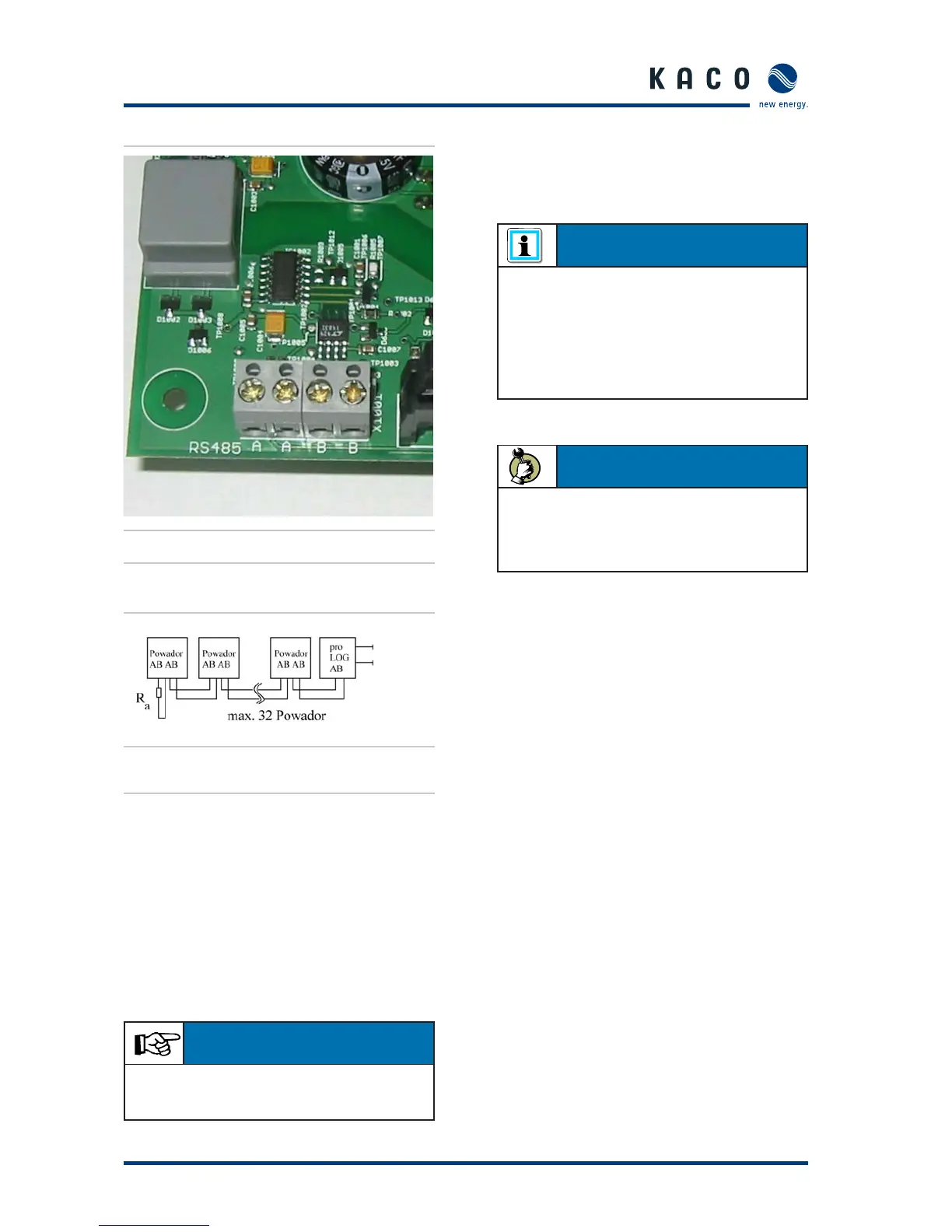
Figure 6.12: Connection diagram for the RS485
interface
In fi gure 6.12, a terminating resistor (Ra) with 330 Ω is con-
nected to the left inverter. For proper signal transmission, the
last unit in a chain must have a terminating resistor. A terminat-
ing resistor is delivered with each Powador inverter.
With a bus system such as the RS485, each device sharing
this bus must possess a unique address, regardless of whether
it is an inverter or a current sensing device. For inverters, the
address range can be selected between 1 and 32. You can
defi ne the address for each inverter using the confi guration
menu (see Operating Instructions).
6.7 Starting up the inverter
After completing the mechanical and electrical installation, the
inverter is put into operation as follows:
The green LED (1) will then light up (provided the generator
voltage is greater than 100 V). The display now shows the
current generator voltage: “Start at 125 V meas. xxx V”. If the
measured voltage is greater than 125 V, the unit begins feeding
into the grid after a country-specifi c time period (see section
4, Technical Data). This start-up period is required in order to
ensure that the generator voltage is continuously above the
power delivery limit of 125 V. A quick start routine is provided
for startup and test purposes. This routine circumvents the
start-up period. This quick start routine is found in the confi gu-
ration mode menu (see Operating Instructions).
During the normal start-up procedure, the line relays audibly
switch on after a country-specifi c time period (see section 4,
Technical Data) and power delivery starts. This is indicated by
the green LED (2). The display now shows the power being fed
into the grid. Key “1” can now be used to display the various
measured values (see Operating Instructions).
If required, the date and time might need to be confi gured once
again (see Operating Instructions).
Section 6 · Installation and Start-up
IMPORTANT
Ensure that the A and B wires are properly connected. Com-
munication is not possible if the wires are exchanged.
NOTE
The inverter can be put into operation only under daylight
conditions (i.e. at a solar generator voltage of > 100 V).
If no daylight or solar generator voltage is present, the
inverter can be activated by pressing the night start-up
key on the underside of the inverter. However, normal
operation is not possible in this condition. Only the values
can be read off the display.
ACTION
Switch on the line voltage (via the external circuit –
breakers).
Switch on the solar generator via the DC disconnector
–
(0 → 1).
 Loading...