- 9 -
KALVIS-4 (N) EN 2019.01.14
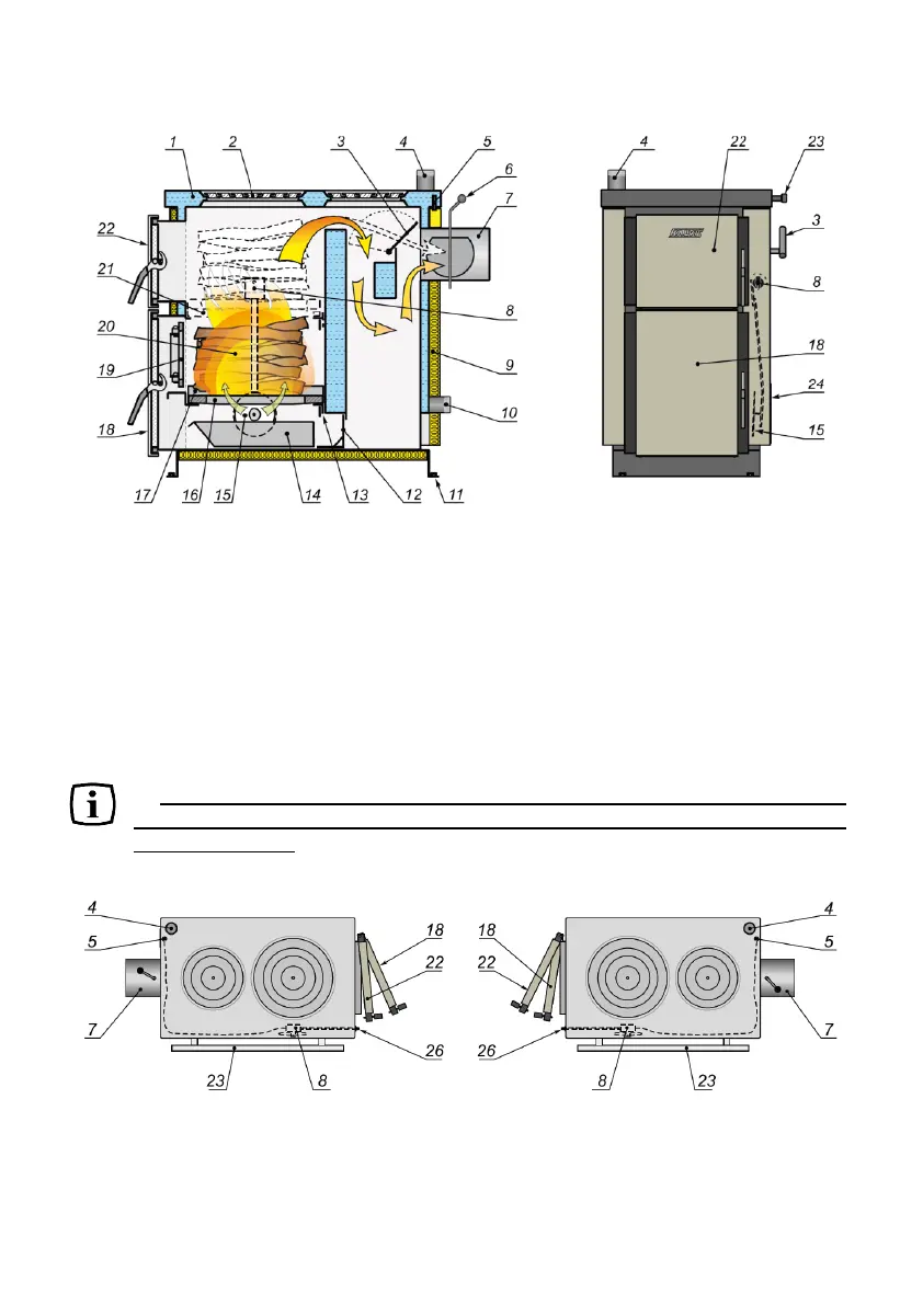
4.2. Design
Fog.1. Boiler design.
1. Frame. 2. Cast iron rings. 3. Firing valve. 4. Outgoing (hot) water branch pipe. 5. Air
draft controller sensor. 6. Smoke draft valve. 7. Flue pipe. 8. Air draft controller.
9. Decorative - thermal insulating panels. 10. A return (cooled) water branch pipe, also used
as a discharge branch. 11. Welded nuts for mounting the boiler to the pallet and height
adjustment during installation. 12. Inserted cleaning cover. 13. Hung firegrate holding
bracket. 14. Ash drawer. 15. Air supply valve. 16. Firegrate. 17. Side supports for firegrate.
18. Combustion chamber door. 19. Inner cast iron door. 20. Combustion chamber.
21. Upper position of firegrate. 22. Charging door. 23. Handrail. 24. Air supply grate.
For your convenience, in order to make the most efficient use of the
premises where the boiler is to be installed, select the most suitable boiler
model (see fig. 2).
Left-hand option Right-hand option
Fig. 2.
4. Outgoing (hot) water branch pipe. 5. Air draft controller sensor. 7. Flue pipe. 8. Air
draft controller. 18. Combustion chamber door. 22. Loading door. 23. Handrail. 26. Air
supply valve adjustment handle.