37KaCool D02.02.2017
Installation and Connection
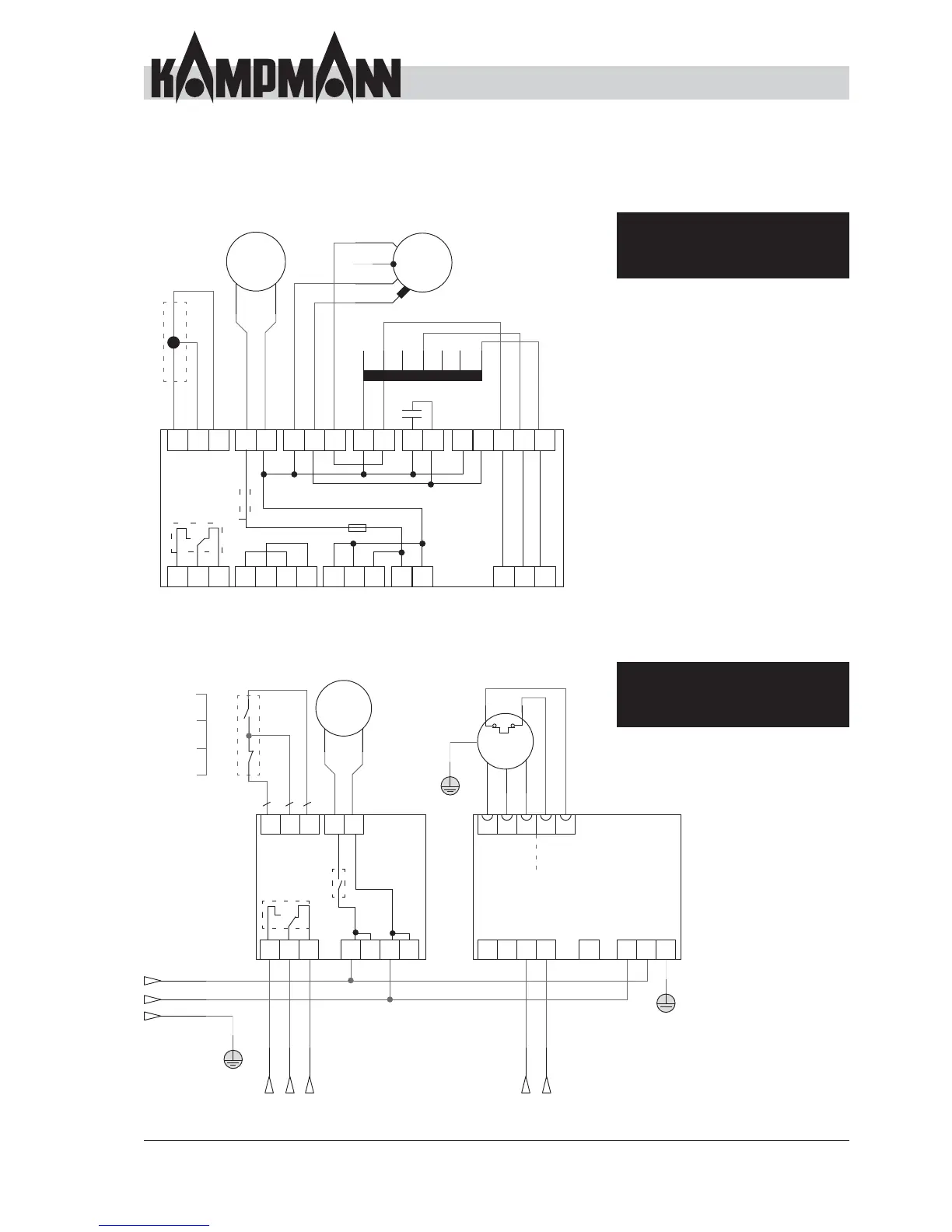
Control overview
1 = Condensation level OK
2 = Condensation pump foot contact
3 = Condensation level too high, fault
4 = Heating valve 4-pipe, foot contact
5 = Cooling valve 2 / 4-pipe, foot contact
6 = Heating valve 4-pipe, foot contact
7 = Cooling valve actuation, 2 / 4-pipe
8 = Neutral wire, heating and cooling valve
9 = Neutral wire, thermostat
10 = Power supply to thermostat
L = Power supply 230 V/50 Hz
N = Neutral wire
V 3 = Maximum fan stage
V 2 = Medium fan stage
V 1 = Minimum fan stage
RL1 = 150 seconds from the liquid falling below
the lower level, pump on (Condensation
pump control)
RL2 = 150 seconds from the liquid falling below
the upper level, alarm on (Condensation
pump control)
J1.1
L
L
L
N
N
M
M
M
1 ~
M
1 ~
Z
NM NM
M3 M7 M6 M2 M1 M4
NM
bn
sw
gnge
bl
C
14
LPC
RL1
RL2 T1.6
AL
SEC1
Condensation pump
Float switch
Fan
J1 J5 J2J4 M5J3
J1.2 CM CM V2LM C
258369L710N
NPCJ1.3 LM V3 V1
V2V3 V1
The cooling valve has to be routed via the
condensation alarm. The valve has to be closed
when the contact changes to fault.
AC fans, electromechanical model
Stand-alone unit, on-site control
EC fans, electromechanical model
Stand-alone unit, on-site control
1 = Condensation level OK
2 = Foot contact
Condensation pump
3 = Condensation alarm
A+ = Signal input
Impedance < 68 KOhm
A- = Signal input
Impedance < 68 KOhm
L = Power supply
230 V / 50 Hz
N = Neutral wire
RL1 = 120 seconds from the
liquid falling below the
lower level, pump on
(Condensation pump
control)
RL2 = 120 seconds from the
liquid falling below the
upper level, alarm on
(Condensation pump
control)
The cooling valve has to be routed via the
condensation alarm. The valve has to be closed
when the contact changes to fault.
15V
Mains power supply:
230 / 50 Hz
(fuse provided by the
customer)
M2
LN
A+
TPTP
PE
U
V
W
TK
TK
PE
M
3 ~
BLACSEP
M3
RLS
RL2
top
bottom
M1
1
J3J1
bn
or
ws
L L NN
J1.1
J1.2 J1.3 LPC NPC
1 2 3 A-
X2
P+P -
L
N
M
1 ~
Condensation pumpFloat switch
UVW
EC fan
Control
0 – 10 V
1)
Condensation alarm
(potential-free)
Alarm
Pump is
enabled
Operation
RL1
0 – 10 V
GND
C
NC
NO
N
PE
L
1)
0 V: Off/ >1,5-10 V: On