KaCool D 02.02.201736
Installation and Connection
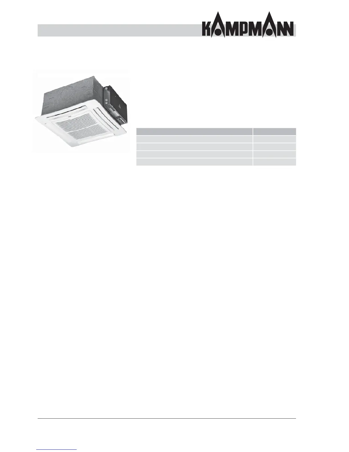
Control overview
6.4 Control overview
The unit is available in a variety of electrical confi gurations. It
can be connected via a receiver PCB in the electrical junction
box. This is located on the opposite side to the unit's water
connection. Refer to the respective wiring diagram for the
wiring, which varies depending on the model.
Example:
325006232001C1 -> KaControl controller
Model Art. no. ending
AC fans, electromechanical model
AC fans, infra-red remote control_W _W
EC fans, electromechanical model
EC fans, KaControl control electronics _C1 _C1