39KaCool D02.02.2017
Installation and Connection
Control overview
AC fans, infra-red remote control
Confi guration: Functions
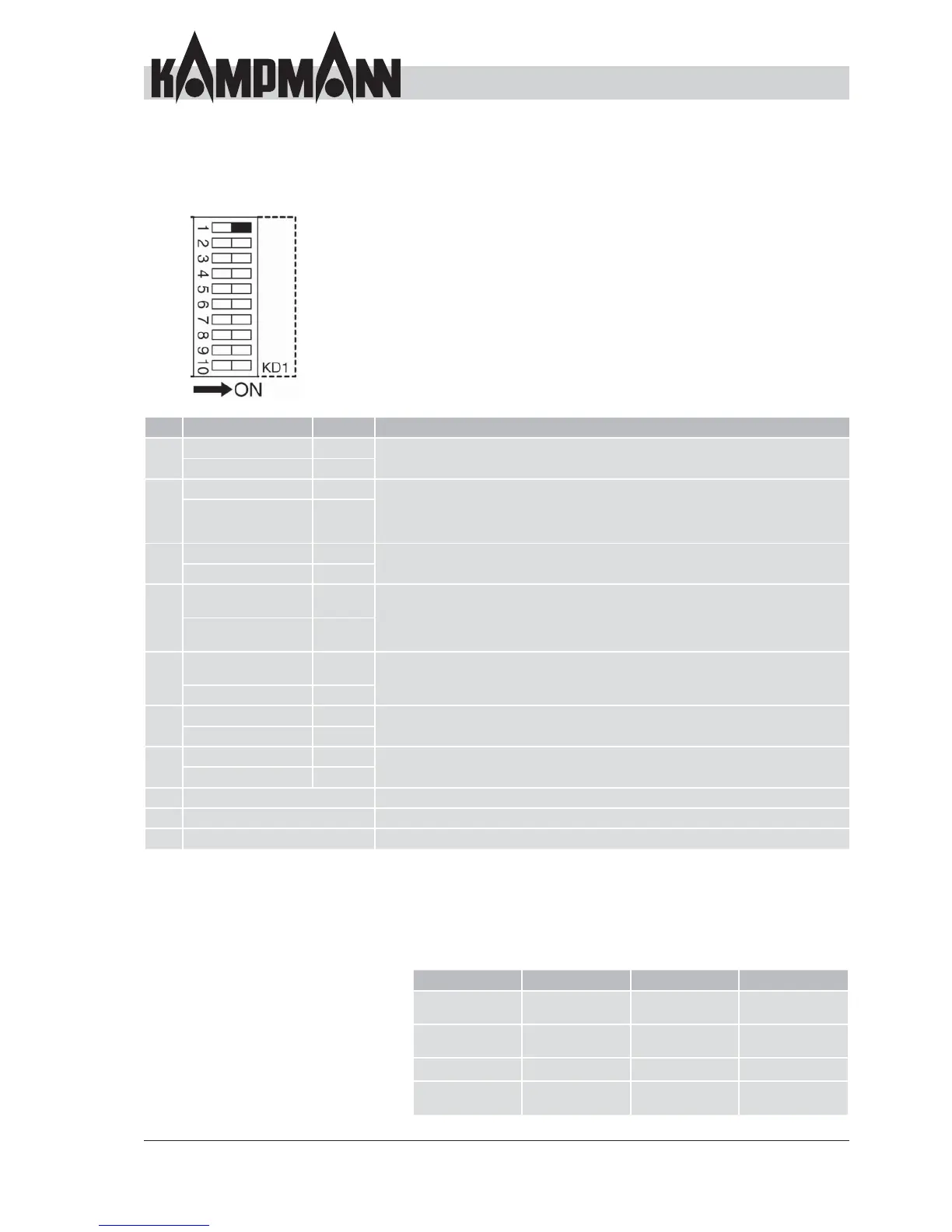
D2 DIP switch for control confi guration
The DIP switches can be used to confi gure the control of the
chilled water cassette (8 and 9 see previous page).
DIP Function Position Description
1 4-pipe system ON The cassette is confi gured as a 2-pipe system (heating or cooling) or 4-pipe system
(heating and cooling) depending on the position.
2-pipe system OFF
Cyclical fan ON The fan always runs in "Continuous fl ow fan" mode whenever the cassette is
supplied with power. The fan stops 3 min. after reaching the room temperature
(and closing the valves") in cyclical fan mode. The fan is operated every 10 min. for
100 sec. to allow room temperature measurement on the air intake sensor.
Continuous fl ow fan OFF
3 Sensor 3 enabled ON
Sensor T3 is located in the heat exchanger. The fan is only enabled when the
temperature is 32 °C or higher.
Sensor 3 disabled OFF
4 Sensor T3, only
heating mode
ON
If sensor T3 is enabled, you can decide in which operating modes
the control function is enabled using DIP 4.
Cooling mode: below 20 °C starts, above 24 °C stops
Heating mode: above 34 °C starts, below 30 °C stops
Sensor T3, heating
and cooling mode
OFF
5 Enable fan with
valve opening
ON
The fan is operated in continuous mode or only when opening the
valves depending on the setting.
Continuous fan mode
OFF
6 Changeover enabled ON
Special function only with optional cassette features (e.g. electric heating element)
in terms of functionality
Changeover disabled OFF
7 Changeover enabled ON
Special function only with optional cassette features (e.g. electric heating element)
in terms of functionality
Changeover disabled OFF
8 See description for inputs/outputs on page 38
9 See description for inputs/outputs on page 38
10 See description for group formation on 40
Fault messages: PCB
The PCB conducts its own diagnosis and shows its status via LED
indicators
LED 1 LED 1 LED 2 LED 3
Fault sensor T1
fl ashing
Flashing
Fault sensor T3
on or fl ashing
On or fl ashing
Input CA open Flashing
Input CF open On or fl ashing
4x long, 2x short