18 Kmstrup A/S • 5512853_C1_GB_01.2017
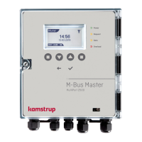
M-Bus Mster MultiPort 250D
4.1 Specil fetures of M-Bus Mster MultiPort 250D
M-Bus Mster MultiPort 250D hs been designed with the newest cble driver technology, nd is, therefore, rther
insensitive to the cpcity of the M-Bus network.
Thus, designing n M-Bus network to be used together with M-Bus Mster MultiPort 250D, the limiting fctor s to
possible cble length will primrily be the cble resistnce in the network.
4.2 Electricl conditions in n M-Bus network
According to EN 13757-2, the mximum output voltge from n M-Bus Mster must not exceed 42 V. The output voltge
from M-Bus Mster MultiPort 250D is 41 V.
• If the voltge mesured over terminls 24-25 is 24 V or more t the most distnt meter, there is high degree of
certinty tht ll meters cn be red.
• If the voltge is between 20 nd 24 V, it will probbly be possible to red ll meters.
• If the voltge is between 18 nd 20 V, the meter my be red.
• If the voltge is below 18 V, it is most likely tht the meter cnnot be red.
There must be no communiction on the M-Bus network when the bove mesurement is mde.
4.2.1 M-Bus modules
Ech M-Bus module lods the M-Bus network too. According to the stndrd, n M-Bus module should lod the
network with 1 unit lod (UL) corresponding to 1.5 mA. Some modules, however, lod with up to 4 UL.
Cpcitively the lod of n M-Bus module is 0.5 – 1 nF.
The number of connected M-Bus slves is shown on the disply of M-Bus Mster 250D. Plese note tht it is not
possible to show the exct number of connected slves. This is due to tolernces in the slves.
4.3 Instlltion prmeters
The following prmeters re essentil to the possible cble length of n M-Bus network.
 Loading...