14
Service and Repair Manual
Model 900/950/990
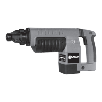
1. Remove the six screws (349, 229), six spring
washers (350, 230) securing the transmitter
housing (369, 242) to the hammer casing (346,
228).
2. Using a soft faced hammer, loosen and remove
the transmitter assembly. The transmitter
assembly contains the anvil assembly and
associated components. Remove the anvil
assembly from the transmitter assembly and
(Model 900 only) the stepped ring (235).
3. Remove the rubber ring (355, 236). Pull the anvil
(357, 238), recoil transfer ring (356, 237) and the
two anvil rings (358,239 ) from the driver
housing (372). Remove the anvil rings and recoil
transfer ring from the anvil.
4. Remove junk ring (373, 240) from driver (372)
(Model 950) or anvil sleeve (Model 900) and
press out the driver bearing (371) from the
transmitter housing.
5. Model 950 only. Using service tool, part no.
9710732701, press the drive shaft bearing (374)
from the transmitter housing (using thick grease
or similar product).
Dismantling
the transmit-
ter housing
(All models,
950 shown)
235
355
236
356
237
357
238
358
239
373
240
371
372
349
229
350
230
346
228
374
369
242
Removing the
driver
(900MV)
1. Remove the six screws (551), nose piece (550),
four balls (552) and trans housing (541).
2. Remove the following items:
- ‘O’ ring (542)
- ‘O’ ring (535)
- seal (543)
- junk ring (544)
- seal (545)
- anvil (546)
- junk ring (547)
- ‘O’ ring (548)
- driver (549)
563
Fig. 4
Fig. 5
Fig. 6
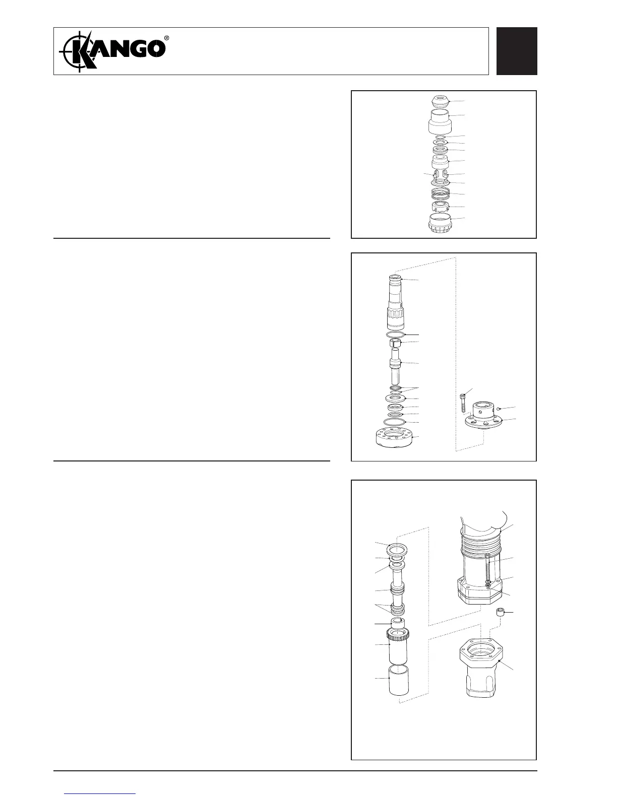
Dismantling
the SDS
assembly
(900MV)
1. Remove end cap (563) and chuck cover (562).
2. Remove the following items:
- wire clip (561)
- buffer stop (560)
- buffer (559)
- SDS chuck (558)
3. Remove two latches (557) and remove the
following items:
- latch plate (556)
- spring (555)
- lock plate (554)
- lock chuck (553)
562
561
560
559
558
557
556
555
554
553
557
352
549
548
547
546
545
544
543
535
542
541
552
550
551