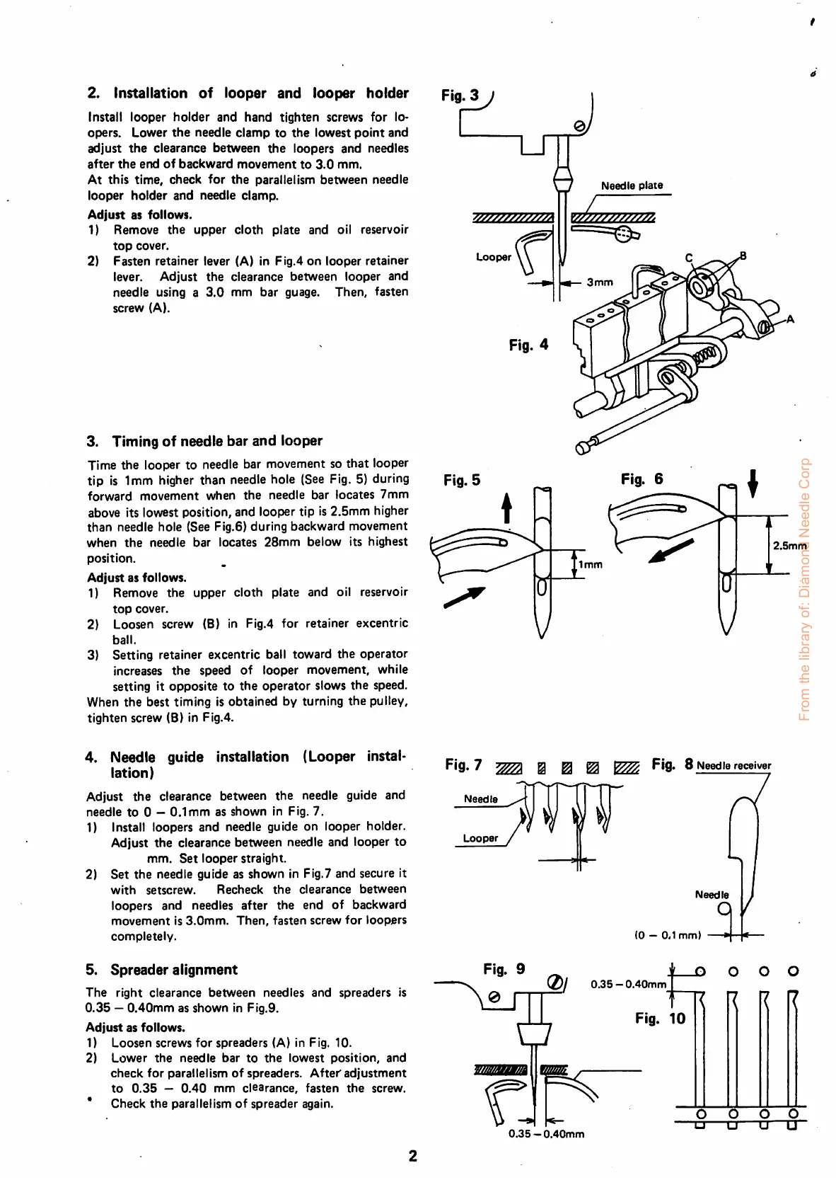
2. Installation
of
looper
and
looper
holder
Install
looper
holder
and
hand
tighten
screws
for
lo-
opers.
Lower
the
needle
clamp
to
the
lowest
point
and
adjust
the
clearance between
the
loopers and needles
after
the
end
of
backward
movement
to
3.0
mm.
At
this
time,
check
for
the
parallelism
between
needle
looper
holder
and
needle clamp.
Adjust
as
follows.
1)
Remove
the
upper
cloth
plate
and oil reservoir
top
cover.
2)
Fasten
retainer
lever (A) in
Flg.4
on
looper
retainer
lever.
Adjust
the
clearance
between
looper
and
needle
using a
3.0
mm
bar
guage.
Then,
fasten
screw
(A).
3. Tlining
of
needle
bar
and
looper
Time
the
looper to needle bar movement so
that
looper
tip is 1mm higher than needle hole (See Fig. 5) during
forward
movement
when
the
needle
bar
locates
7mm
above its lowest position, and looper tip is
2.5mm
higher
than
needle hole (See Fig.6)
during
backward
movement
when
the
needle
bar
locates
28mm
below
its
highest
position.
Adjust
as
follows.
1) Remove
the
upper
cloth
plate
and oil reservoir
top
cover.
2) Loosen screw (B) in Fig.4
for
retainer
excentric
ball.
3)
Setting
retainer
excentric
ball toward
the
operator
increases
the
speed
of
looper movement, while
setting it opposite to
the
operator
slows
the
speed.
When
the
best timing is
obtained
by turning
the
pulley,
tighten
screw
(8)
in Fig.4.
4. Needle guide Installation (Looper instal
lation)
Adjust
the
clearance between
the
needle guide and
needle
to
0 —
0.1mm
as
shown
in Fig. 7.
1) Install loopers and needle guide on looper holder.
Adjust
the
clearance
between
needle
and
looper
to
mm.
Set
looper
straight.
2)
Set
the
needle guide as shown in Fig.7 and secure it
with
setscrew.
Recheck
the
clearance
between
loopers and needles after the end of backward
movement
is
3.0mm.
Then,
fasten
screw
for
loopers
completely.
5.
Spreader
alignment
The
right
clearance
between
needles
and
spreaders
is
0.35
—
0.40mm
as
shown
in Fig.9.
Adjust
as
follows.
1) Loosen screws
for
spreaders (A) in Fig. 10.
2)
Lower
the
needle
bar
to
the
lowest
position,
and
check
for
parallelism
of
spreaders.
After
adjustment
to
0.35
—
0.40
mm
clearance,
fasten
the
screw.
* Check the parallelism of spreader again.
Looper
P'9. 7 @ ^
1^
FiO'
8
Needle
receiver
Needle
Looper
/
Fig. 9
Needle
plate
3
mm
2.Smm
Needle
(0
—
0,1
mm)
0.35
—
0.40mm
D O O O
Fig.
10
0.35
—0.40mm
O O O O
T3
D •
•"
From the library of: Diamond Needle Corp
 Loading...