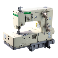
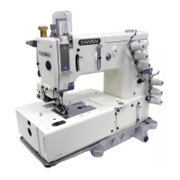
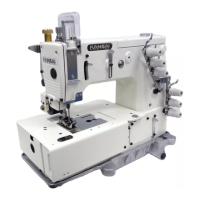
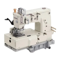
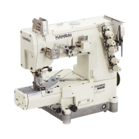
This document provides a comprehensive guide for the NC Series Industrial Sewing Machines, including parts lists and instruction manuals for various models such as NC1103-4G, NC1001GJ, NC1001GSJ, and NC1001GSJF. The content is structured to cover machine adjustments, maintenance, and operational procedures.
The parts book, published in September 2018, is based on data current as of November 2018. It is organized with exploded illustrations on left-hand pages and corresponding part numbers, names, and quantities on right-hand pages. A parts number index is included at the back for easy reference. Users are advised that parts are subject to change without prior notice.
The NC Series machines are categorized by their features:
- NC1103: Equipped with a top cover thread (上飾り付).
- NC1003: Without a top cover thread (上飾り無し).
- UTA: Features a pneumatic thread trimmer unit (エアー式糸切装置付ミシン).
- UTE: Features an electric thread trimmer unit (電気式糸切装置付ミシン).
- UTAB: UTA with an air wiper without top cover thread trimmer (UTAのエアーブロー式糸切装置付ミシン).
- CL: Designed for covering operations (standard/fold-down) (カバーリング用).
- DA: For plain seaming and hemming operations (地縫い及び裾引き用).
- SJ: For hemming trouser bottoms and sleeves on jeans wear with a tractor foot (トラクター押え付 ジーンズ裾三巻用).
- SJF: Features an openable rolled hemming folder, enclosing a fixed folder (開ホルダー付).
- J: For rolled hemming bottoms operation with a side roller mechanism (サイドローラー付 裾三巻き用).
- CD: Equipped with a stitch condensing device (コンデンス付き).
Needle width is specified in inches.
Machine Speed and Operating Direction
The machine pulley rotates clockwise, matching the handwheel's direction. For optimal machine life, it is recommended to run the machine at 15-20% below the maximum speed for the first 200 hours (approximately one month), then transition to the standard speed.
NC1103:
- Maximum Speed: 4,500 rpm
- Standard Speed: 4,000 rpm
NC1001J:
- Maximum Speed: 3,500 SPM
- Standard Speed: 3,000 SPM
NC1001SJ:
- Maximum Speed: 4,000 SPM
- Standard Speed: 3,500 SPM
The motor is a 3-phase, 2-pole, 400W clutch motor, using an M type V belt. The motor pulley's outer diameter should be selected based on the desired machine speed. Proper belt tension is achieved when a 1-2 cm deflection occurs by pressing the finger onto the middle of the belt.
Lubrication
The machine uses Kansai Special's genuine oil (Part No. 28-618: 700cc). To fill, remove rubber plug A from the oil hole and fill until the oil level reaches the top line (H) on oil gauge C. Subsequent oil additions should maintain the level between H and L. After filling, run the machine to ensure oil splashes to oil flow sight window B.
For extended machine life, replace the oil after the first 250 hours of operation. This involves removing the V belt and the machine from the table, then draining the oil by removing screw D. After draining, retighten screw D and refill with new oil.
The oil filter element (E) should be cleaned every six months to prevent improper oiling. If oil flow from the nozzle is insufficient, remove oil filter cap F and replace the element if necessary.
Sewing Machine Installation
The NC Series can be installed in non-submerged or semi-submerged configurations.
- Non-submerged: Install the machine by securing bolts and nuts to the table, fitting rubber cushions onto the bolts, and then mounting the machine.
- Semi-submerged: Secure oil reservoir installation brackets to the table with screws, fit rubber cushions onto the screws, and then mount the machine.
Needles & Threading
The machine uses UY128GAS needles from Schmetz, Organ, or Groz-Beckert.
- Needle Sizes: #09 (Nm65), #10 (Nm70), #11 (Nm75), #12 (Nm80), #14 (Nm90).
- For NC/J,SJ Series: TVx5 needles from Schmetz, Organ, or Groz-Beckert.
- Needle Sizes: Nm120 (#19), Nm125 (#20), Nm130 (#21).
When replacing the needle, ensure the scarf faces the rear of the machine. Always turn off the power before replacing needles. For clutch motors, continue pressing the pedal until the machine stops completely.
Threading should follow the provided illustrations to prevent skip stitching, thread breakage, or uneven stitch formation. Thread tension should be adjusted based on thread type and feeding amount. To thread the looper thread support plate, press lever A to raise support plate B, then return it by pressing B. Ensure the support plate B is correctly returned before starting the machine.
Timing of the Looper to the Needles
- Needle Bar Stroke: The standard needle bar stroke is 33mm. To change it, loosen screws A and turn needle bar link C. Bring flat surface D to the top or bottom. When the needle bar and flat surface D are at their highest position, the stroke is 33mm. Retighten screws A securely after adjustment.
- Needle Height: When the needle bar is at the bottom of its stroke, remove the head cover plug, loosen screw A, and adjust the needle bar up or down. Setting distance B varies with needle stroke or gauge size.
- NC1001J: 15.0mm
- NC1001SJ: 12.4mm
- Looper Angle and Height: Insert the looper fully into looper holder A and tighten screw B. The proper angle is 2°30' against the feed direction (for NC/J,SJ Series, 90° against feed direction). The distance from the looper point to the extension line from the looper blade bottom should be approximately 1.1mm (for NC/J,SJ Series, ensure it's not more than 90°).
- Looper Setting Distance: When the looper is at its farthest right position, the looper setting distance (from looper point to needle center) should be 6mm. This distance (X) varies with needle stroke and gauge size.
- 3.2 (1/8) inch: 8.2±0.2 mm (31 stroke), 9.7±0.2 mm (33 stroke)
- 4.0 (5/32) inch: 7.8±0.2 mm (31 stroke), 9.3±0.2 mm (33 stroke)
- 4.8 (3/16) inch: 7.4±0.2 mm (31 stroke), 8.9±0.2 mm (33 stroke)
- 5.6 (7/32) inch: 7.0±0.2 mm (31 stroke), 8.5±0.2 mm (33 stroke)
- 6.4 (1/4) inch: 6.6±0.2 mm (31 stroke), 8.1±0.2 mm (33 stroke)
- NC1001J: 3.8mm
- NC1001SJ: 5.0mm
The looper point should pass the center of the left needle and be 1.3-1.6mm above the top of its needle's eye when moving to the left on the back side of the left needle.
- Needle/Looper Front-to-Back Relationship: When the looper point moves to the left needle, the distance (Y) from the top of the needle's eye to the looper point should be adjusted. To adjust, remove the machine cover, loosen screws A on the upper timing pulley, and shift the pulley by turning the handwheel while holding the pulley.
The clearance between the looper point and the back side of the needle should be 0-0.05mm. Adjust by loosening screw B on eccentric A and shifting timing mark C.
- Looper Front-to-Back Movement: The clearance between the left needle point and the looper's back side when the looper moves right from its extreme left travel should be 0.3-0.6mm (needle pressed back). The distance from the left needle point to the looper's eye center on the back side should be 3-3.5mm. Factory setting is for #11 (Nm75) needles. For Nm80-90, adjust as required. Loosen nut B while holding screw A with a screwdriver, then move the front-to-back rod. Moving alignment mark D forward increases the amount, backward decreases it.
Front and Rear Needle Guards
- Rear Needle Guard Position: Align line 'a' with the center of the needle's hole when the needle is at the bottom of its stroke. The clearance between the needle and looper should be 0-0.05mm when the looper point reaches the right needle (R). Loosen screw B and move needle guard A slightly forward to achieve 0-0.1mm clearance between the left needle (S) and needle guard (A). Loosen screws C for front-to-back adjustment, and screw B for vertical and angle adjustment.
- Front Needle Guard Position: When the looper reaches the center of the left needle, the front needle guard height should be 1.5-2mm from the tip of left needle Y to the line of needle guard X. The clearance between the needle guard and needles should be 0.1-0.3mm. Loosen screws B for front-to-back adjustment, and screw A for vertical and angle adjustment.
Spreader
- Spreader Timing: Adjust based on thread and conditions. Remove top arm cover, loosen two screws for looper eccentric A on the upper shaft, and shift alignment mark C (front/back) relative to alignment mark B. Shifting C towards D advances timing, towards E delays it.
- Spreader Position:
- Height: Distance from left needle point to spreader bottom surface should be 1mm.
- Left-to-Right: When spreader is at extreme left travel, distance from center of left needle to thread carrying notch should be 4.5-5.5mm. When spreader passes left needle, clearance between thread carrying notch and left needle should be 0.5-0.8mm. Loosen screws A and B for adjustment.
- Spreader Thread Take-Up: When needle bar is at top stroke, thread any part on spreader thread take-up with spreader thread.
- Spreader Movement Amount: Adjust based on spreader threads and fabric weight. Remove arm top cover, loosen nut C, and move adjusting lever pin (a) to decrease, (b) to increase.
Feed Dogs & Stitch Length
- Feed Dog Height & Tilt: When feed dogs are at top stroke, right and left feed dogs should be parallel and 1-1.2mm above the needle plate. For NC/J series, loosen screws E and F to adjust feed dogs up/down. Bottom face B of left feed dog A should touch top face D of right feed dog C. For NC/SJ series, loosen screws E and F to adjust front and rear feed dogs up/down.
- Guide Plate (NC/J series): Two types for different thicknesses. Standard thickness C is 2.3mm, distance from needle center to right side E is 2.5mm. 1.8mm thickness D is also available.
- Tilt Adjustment: Open front cover, remove cloth plate B. Loosen screw C with 3mm key wrench. Remove cylinder cover. Use wrench on screw D. Turn shaft of front side towards front to tilt front feed dog rear end up, towards back to tilt front end down.
- Stitch Length: Adjustable from 1.4 to 4.2mm.
- To increase, turn adjusting knob A clockwise. To decrease, turn counterclockwise.
- To adjust with lever B, secure with nut C. Range extends from reading by lever B when knob A is turned to stopper D.
- Differential Feed: NC/J series uses left and right differential feeding. Open front cover A, loosen screw B. Move B up for maximum normal differential feed ratio (1:1.4), down for maximum reverse (1:0.8). NC/SJ series uses front and back differential feeding. Move B up to gather fabric, down to stretch fabric. When alignment mark C aligns with screw B center, ratio is 1:1.
- Presser Foot Pressure: Should be light enough for uniform stitches. Turn adjusting knob clockwise to increase pressure.
- Presser Foot Position & Lift: Fit presser foot so needle drops correctly into its hole. Loosen screw A, adjust left/right.
- Lift: For machines with spreader, 6mm above needle plate. Without spreader, 8mm above needle plate. Set stopper B, fasten lever with nut C.
- NC/J series: Presser foot A synchronized with side roller E. Adjust amount by loosening screw K and adjusting connecting plate J up/down. Presser foot should be 7.5mm above guide plate.
- NC/SJ series: Presser foot should be 9mm above needle plate. Set stopper B, fasten lever with nut C. Adjust clearance between needle plate and foot bottom by loosening nut E and moving screw D.
- Float Foot: Turn adjusting screw D clockwise/counterclockwise to adjust presser bar lifting lever. If not used, move screw E to top.
Roller Belt Tension Adjustment (NC/J series)
- Tension Adjustment: Loosen screw D and turn collar E to adjust spring F strength. Loosen nut H and adjust screw G to adjust roller C pressure. Move puller base bracket A front/back. Moving it back increases timing belt tension, moving it front loosens it.
- Needle Thread Guides Position: Distance from eyelet center to set screw should be 17.5mm. Loosen screws A, adjust height.
- Thread Guide on Needle Thread Take-Up: When needle bar is at bottom stroke, take-up bracket A should be level. Distance from shaft center to thread guide B should be 75mm. Loosen screws C and D. Move take-up to Y to tighten, to X to loosen.
- Needle Thread Take-Up Timing: Rod ball factory-set at 5.5mm from shaft rear end. Move rod ball forward to make loop small, backward to make loop large. Remove rubber top plug, loosen screw A with 5mm wrench, move rod ball.
- Needle Thread Guide Position: When needle bar is at bottom stroke, needle bar eyelet A center should be level with thread guide B top surface. Move B up for large loop (stretchable threads), down for small loop. Loosen screw C, move B up/down. Loosen screw E, move D up/down.
- Looper Thread Take-Up Position: When left needle descending to looper back side reaches 1-1.5mm above looper blade bottom, looper thread should be removed from position B on take-up.
Hemming Folder Adjustment
- Hemming Width: Adjustable within the range of 1.5-2.5 (10-12).
- Fixed Rolled Hemming Folder: Standard on NC/J and NC/SJ series.
- Openable Rolled Hemming Folder: Standard on NC/SJF series. Also available in accessories box. Can change from openable to fixed by loosening screws A, B, and C.
Thread Trimmer (NC-UT series)
- Usage: Do not use without fabric under presser foot. Press pedal toe (A) to start, release (B) to stop. If needle stops at bottom, press heel (C) to raise. If needle stops at top, thread trimmer actuates. Returning pedal to B lowers presser foot.
- Position Detector Installation: Install detector A, tighten screw B temporarily. Fit positioner bar C onto guide groove, tighten screw D. Turn on motor. Remove trimmer cylinder connector, ensure knife retracted. Press pedal heel after 2-3 stitches. Loosen screws B, align mark P on handwheel E with arm mark. Tighten screws B.
- Air Cylinder Stroke (UTA): Stroke 15mm. Loosen collar B, screw A. Clearance between rubber cushion F and cylinder rear end 15mm. Loosen nut C, position shaft E. With cylinder retracted, distance from bracket D left end to shaft E center 55.3mm.
- Air Cylinder Return Spring: With plunger protruded, slight clearance between collar G and bracket D.
- Solenoid Stroke (UTE): Stroke 15mm. Remove rubber cover F, loosen nut A. Clearance between rubber cushion B and solenoid rear end 15mm. Loosen nut C, position shaft E. With solenoid retracted, distance from bracket D left end to shaft E center 55.3mm.
- Solenoid Return Spring: With plunger protruded, 42mm clearance between collar H and bracket D. Loosen screw G.
- Movable Knife & Stationary Knife Position:
- Movable Knife Position: Set movable knife A (a1) parallel to stationary holder G (g1). Distance from movable knife A point to left screw H center approx. T (73.5mm for NC UTA, UTE; 74.5mm for NC J series UTAB).
- Relation: Adjust engagement between blade (a3) for looper thread and stationary knife to U (2.5mm for NC UTA, UTE; 1.5mm for NC J series UTAB). Blade (a2) for needle thread should pass corner (b1) of stationary knife B.
- Looper Thread Clamp Spring: Position spring D so (a1) of movable knife and (d1) of spring are on same plane. Protrusion V (2mm for NC UTA, UTE; 3.3mm for NC J series UTAB) from movable knife A point when knife is at extreme right. Adjust pressure by turning screw E.
- Movable Knife Pressure Spring: Position spring F so (a1) of movable knife and (f1) of spring are on same plane. Protrusion W (6.2mm for NC UTA, UTE; 7.5mm for NC J series UTAB) from movable knife A point when knife is at extreme right.
- Stationary Knife Holder Stopper: Stopper J stops holder I. Holder I should not slide too far left. Adjustment by loosening screw K, moving stopper left/right. Standard: stopper left end 1mm right from base plate R left end.
- Movable Knife Holder Left & Right: With movable knife A at extreme left travel, distance A (22mm for NC; 24.6mm for NC J) from needle bar center to knife point. Loosen nut T, move pin S by turning nut T. Knife point should be center between looper point and looper eye when knife moves extremely left.
- Movable Knife Front to Back: Center knife point over looper with knife point 12mm left from looper right end. Loosen screw U, turn guide lever ring P clockwise to move knife point forward, counterclockwise to move backward. Holder guide N should slightly touch movable knife holder end.
- Movable Knife Up & Down: Clearance 0mm between movable knife and looper top surface. Loosen screw X, move stationary knife holder guide.
- Relationship between Movable Knife, Needle Thread, Looper Thread: Movable knife A should enter needle thread loops B. Cutting edge C for looper thread should pass looper thread D. When returning, needle and looper threads are pulled right by cutting edges E and F, cut by stationary knife.
- Looper Thread Clamp Spring Pressure: Spring H holds looper thread after cutting. Adjust pressure by turning screw G. Factory set for spun thread (#60) at 90g.
- Thread Releaser Block: With air cylinder rod at left end, clearance between bracket A and releaser block B is 4mm.
- Thread Releaser Connection Plate: Fit plate D to guide screw E. Clearance between plate D and releaser connection lever G.
- Thread Releaser Lever: Position lever F so tension disk opens fast.
- Thread Releaser Plate: Install bar D to plate F with screw G. Bar D top end should protrude 39mm from guide E top surface. Clearance 4mm between washer H and guide E.
- Thread Releaser Hook: Loosen screw I, adjust hook J. Raise hook to decrease thread supplied, lower to increase.
- Safety Detector: Switch A must be pressed (ON) during sewing. Adjust by loosening screws B and E, moving brackets C and D.
- Speed Controller & Air Pressure (UTA, UTAB): Controller F controls speed when knife holder protrudes, G when it retracts. Regulator 4-5kg/cm².
- Air Wiper Adjustment:
- NC-G UTA series: When needle bar is at top stroke, air blowing outlet B 1-2mm below left needle's eye. Loosen screw D. Position B 0.5-1.5mm from needles back side. Loosen screw C. Adjust amount by screw E.
- NC-GJ, GSJ UTAB series: Same as above. Adjust wiper blowing air by screw E, needle cooler blowing air by screw F.
- Thread Wiper Adjustment (UTE): Tighten screw E to position lever B horizontally. Clearance 0-0.3mm between bracket C and stopper ring D. Position wiper K with screw H. Distance from wiper left end to needle bar center 15mm. Clearance between needle center and wiper point P 1mm. Distance between left needle and wiper K 0.5mm with screw A. Wiper K parallel with flat spring M with screw L.
- Presser Foot Lift: Spreader 6mm above needle plate. Without spreader 8mm above needle plate. Loosen screw D, move bracket C up/down.
- Top Cover Thread Trimmer:
- Movable Knife & Stationary Knife: When movable knife E retracts, clearance between mount bracket B and air cylinder C end 8mm (UTA). Clearance between fixed knife G end and movable knife E top 2mm. Loosen screw A, F.
- Clamp Spring: Spring H parallel and same line with stationary knife G end. Loosen screws I.
- Rear Spring: Spring J parallel and set 4mm from stationary knife G end. Loosen screws I.
- Clamp Pressure: Spring H holds top cover thread. Adjust pressure by turning screw K.
- Movable Knife Left & Right: Movable knife C should pass clearance B between spreader A and left needle. Loosen screw H.
- Movable Knife Front to Back: Movable knife should hook top cover thread when returning. Loosen screws J. Clearance between hook end D and top cover thread 1mm.
- Movable Knife Height: When movable knife is at bottom travel, hook point X aligned with spreader top surface. Tighten screws F.
- Condensed Stitch Mechanism (NC/CD series):
- Air Cylinder Position: Available with UTAB. For GJ series, air cylinder A for side roller and air cylinder F for feed mechanism work together. Air cylinder A moves side roller D slightly up to create gap E between needle plate. Loosen screw C, adjust air cylinder A position. Air cylinder F shortens feed dog travel. For GSJ series, only air cylinder F is activated. Works when pedal is pushed back.