CONNECT COMPUTER
6
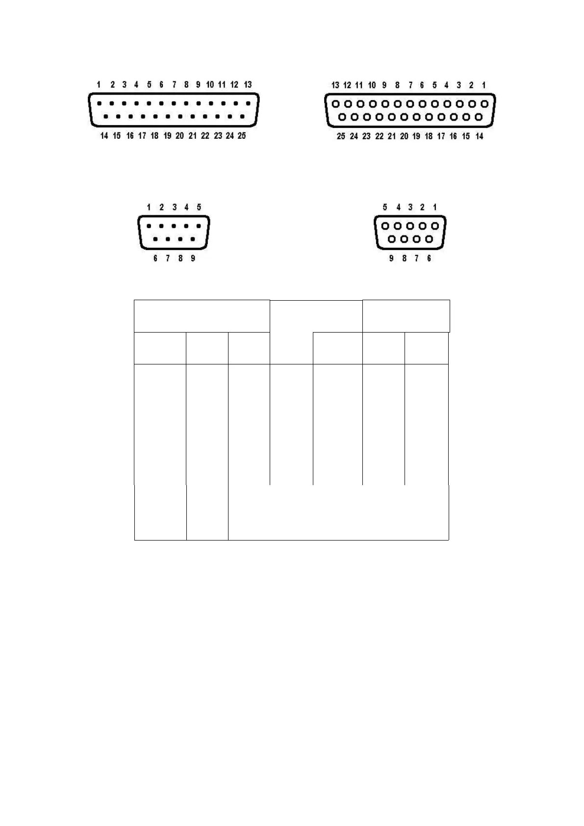
DB-25 Connector
Female (Looking at Holes)
DB-9 Connector
Female (Looking at Holes)
FG*
TXD
RXD
SG*
RTS
CTS
DCD
DSR
DTR
black
white
red
orange
green
brown
yellow
blue
purple
(KAM) To external scope, if desired
(KAM) To external scope, if desired
(KPC-2) DO NOT CONNECT TO COMPUTER
DO NOT CONNECT TO COMPUTER
*FG (Frame Ground) and SG (Signal Ground) are tied together in the TNC. The shield is on pin 1
of the DB-25 and on pin 5 of the DB-9. The black wire is not connected in the KPC-4 serial cable.
The functions of these lines are explained below:
Transmit Data. This line is the serial data from the terminal which is to be transmitted to the other
station by the TNC. It is this line which is used for all communication from your terminal to the
TNC, including commands.
Receive Data. This line is used by the TNC to send the data it receives from the other station to
your terminal. This line is also used to send TNC messages to your terminal.