CONNECT RADIOS
11
Connecting Your Radios
The TNC is attached to your transceiver(s) via the radio Connector(s) on the back panel. (See
page 3 for back panel diagrams.) The KPC-2 and KPC-2400 each have one DB-9 connector labeled
RADIO, which is used for either VHF or HF. The KPC-1 has one 5-pin DIN connector labeled RA-
DIO, which is used either for VHF or HF. The KAM has a DB-9 connector labeled VHF RADIO and
an 8-pin DIN connector labeled HF RADIO. The KPC-4 has two DB-9 connectors for VHF/UHF radio
connections labeled PORT 1 and PORT 2.
Pre-wired cables are provided with the appropriate connector for the TNC port. Two cables come
out of the connector. One with a speaker plug attached, to be plugged into the transceivers exter-
nal speaker jack. You will need to provide the mic-jack connector for your transceiver and wire the
connector to the other cable. Lines from this connector are used to control the PTT function of the
transceiver, input AFSK tones from the TNC and provide other alternate Inputs/Outputs as
described. The KPC-1 comes with two separate cables. One for audio with speaker plugs on both
ends. The other cable has a 5-pin DIN connector on the end for the KPC-1 and you will need to
provide the mic-jack connector for your transceiver and wire it to the other end of this cable.
Some rados may require adjustment of the AFSK Output Levels or Equalization of the received sig-
nals. See the AFSK Output Level and Calibration/Equalization sections for information.
Caution: Check your transceiver manual to correctly wire the corresponding pins of the transceiver
mic-jack.
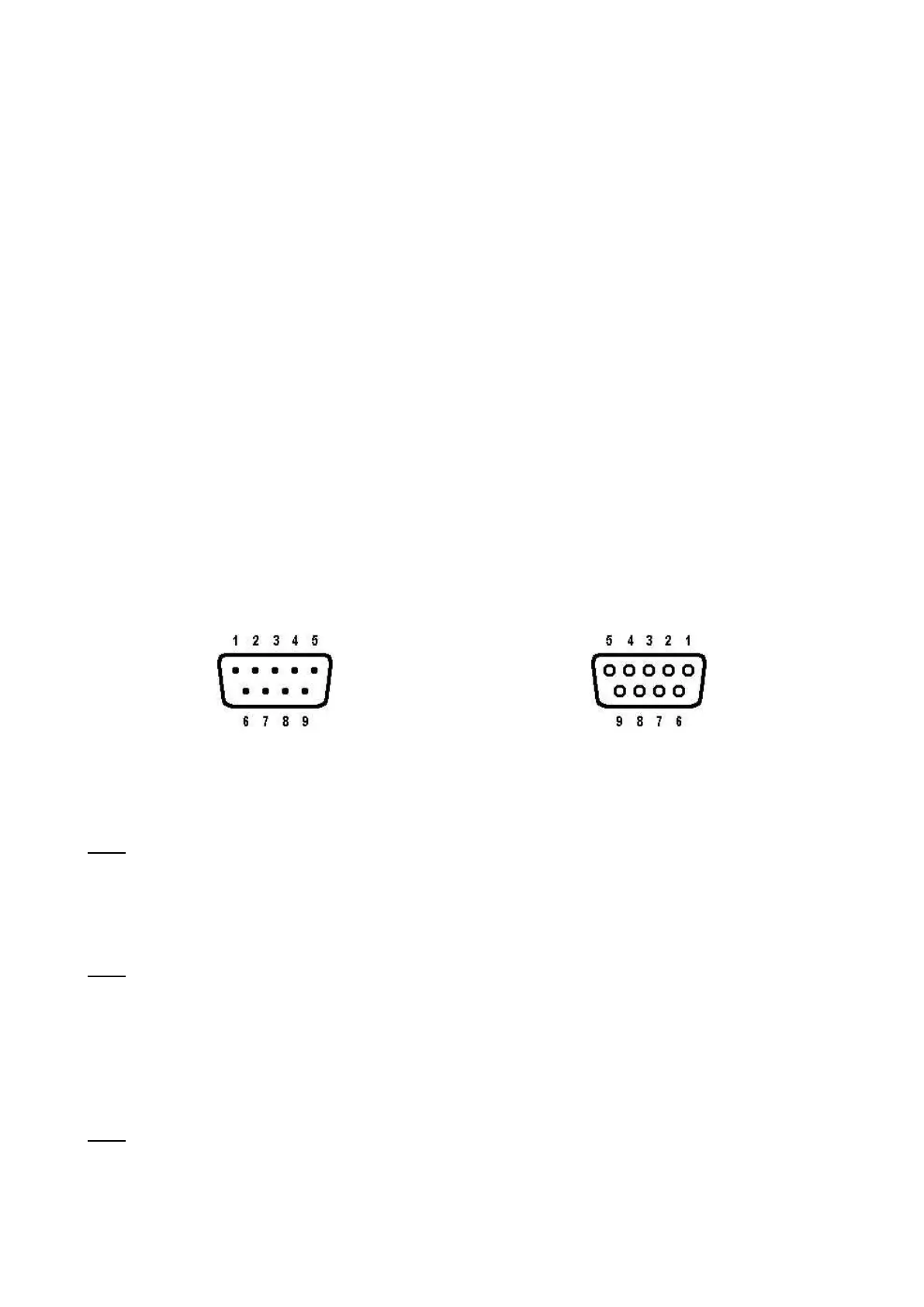
DB-9 Radio Connector
Female (Looking at Holes)
Pins 1, 3, 5 and 6 must be connected to your radio.
Pin 1 – AFSK Out – white lead
This lines carries the AFSK tones generated by the TNC to the Audio Input (microphone) line of
your transceiver. If your transceiver provides a DC voltage on its microphone input, you must iso-
late this voltage from the TNC. This is normally true for hand-held radios. (See the Interfacing
Hand-Held Radio section.)
Pin 2 – XCD – yellow lead
This line may be used to connect the squelch line from your VHF transceiver if desired. This con-
nection will not normally be required, nor used, unless operating on a shared voice channel. Nor-
mally the TNC detects other signals by using its internal software to determine if data is present. If
this pin is connected, a ground potential on this pin will tell the TNC that a signal is present (even
if there is no data) and therefore prevent the TNC from transmitting until the signal is no longer
present. (See the CD parameter in the Commands Manual.)
Pin 3 – Push-To-Talk – brown lead
This line controls the PTT line in your transceiver, allowing the computer to switch the transceiver
from/to transmit or receive. Connect directly to the PTT line of the mic-jack connector (See the
section on Interfacing Hand-Held Radios for special notes concerning this pin.)