SCOPE MONITORING
29
Scope Monitoring
KAM only
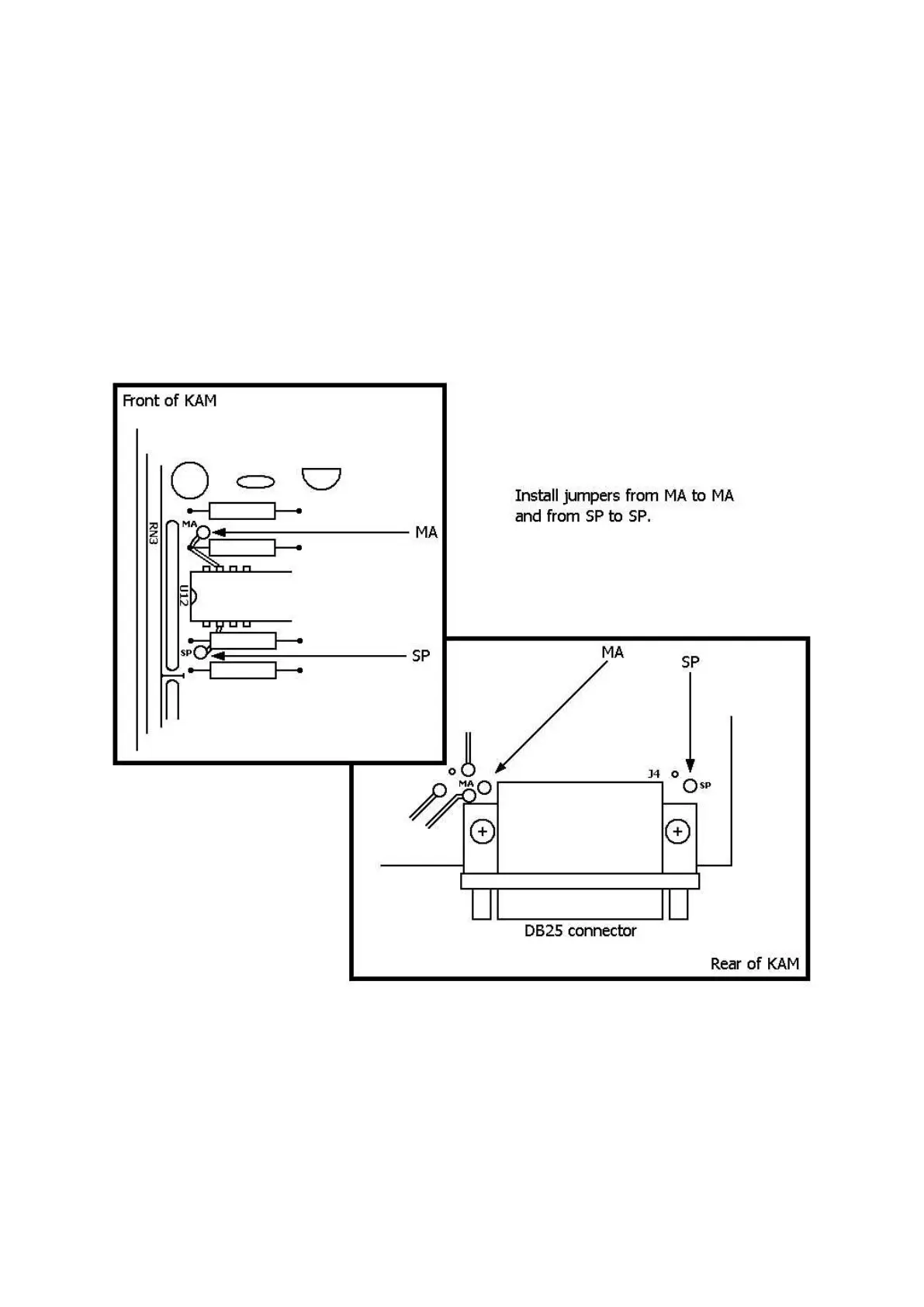
Obtaining Mark and Space Outputs
The schematic diagram of the KAM indicates that Mark and Space outputs are available on pins 11
and 18 of J4 (DB-25 connector). Provisions have been made for obtaining these outputs AFTER in-
stalling jumpers between the points provided on the PC board. This is accomplished by locating
the four holes in the board marked MA and SP and adding wire jumpers between them. One pair
of holes marked MA and SP are located next to the DB25 connector (J4) and the other pair is lo-
cated on the opposite end of the board. Install jumpers from MA to MA and SP to SP and
Mark/Space signals will then be present at pins 11 and 18 of J4. It is advisable to install a 100 kΩ
resistor in series with these lines to protect the KAM from external voltages.