“The Right Control for Your Application.”
12095 NW 39 Street, Coral Springs, FL 33065-2516
KB Electronics, Inc. Phone: 954-346-4900; Fax: 954-346-3377
(A40288) - Rev. E - 6/6/2005 - Z3562E00 Page 14 of 20
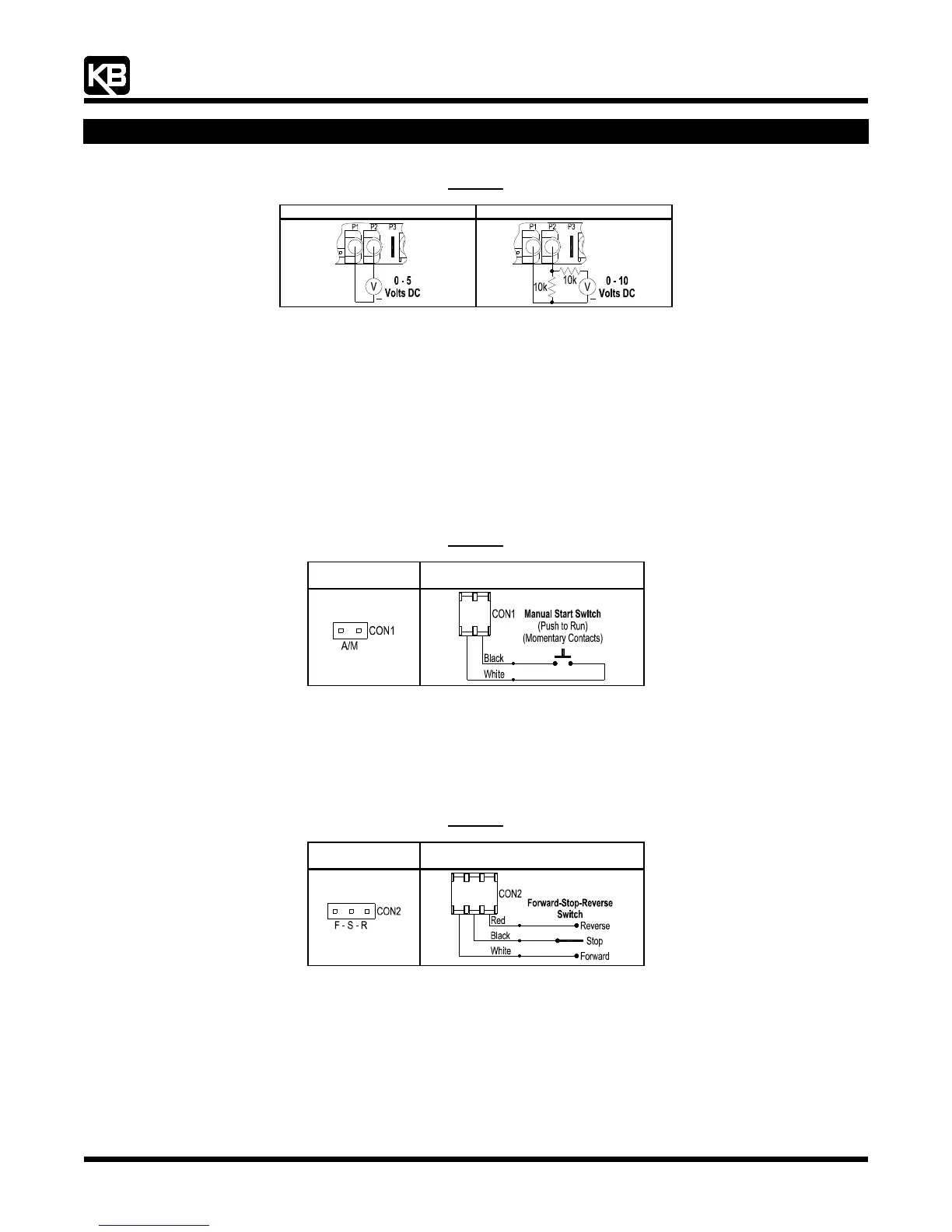
Figure 18
Voltage Following Connection
0 - 5 Volts DC (Isolated) 0 - 10 Volts DC (Isolated)
+
+
9.6 Manual Start Switch Connection (CON1): The Manual Start Mode is used to manually start the drive or restart the drive (reset) if a
fault has occurred. To operate the drive in the Manual Start Mode, remove the factory installed jumper on CON1 and install the 2-
wire connector (supplied). CON1 is located on the lower PC board. The connector must be wired to a momentary switch or contact,
as shown in
Figure 19, on page XX.
In the Manual Start Mode, the drive will trip due to all faults (Overvoltage, Undervoltage, Short Circuit, and I
2
t) and remain tripped
even when the fault is cleared. To Start/Reset the drive, the switch or contact must be manually closed. Also, the drive must be
restarted each time the AC line is interrupted.
For Automatic Start, see
Section 6.3, on page XX.
Notes: 1. See
Section 11.2, on page XX. Also see Section 12.2, on page XX. 2. The drive can be factory programmed for Run/Stop operation with
momentary contacts.
Figure 19
Manual Start Switch Connection
Jumper Removed
Connector Installed for
Manual Start Switch
9.7 Forward-Stop-Reverse Switch Connection (CON2): To operate the drive using a Forward-Stop-Reverse Switch, remove the
factory installed jumper on CON2 and install the 3-wire connector (supplied). CON2 is located on the lower PC board. The
connector must be wired to a "maintained" switch or contact. See
Figure 20, on page XX. Also see Forward/Reverse Speed
Selection, in
Section 6.4, on page XX.
Note: The drive can be factory programmed for momentary contact operation.
Figure 20
Forward-Stop-Reverse Switch Connection
Jumper Removed
Connector Installed for
Forward-Stop-Reverse Switch
9.8 Enable Switch Connection (CON2): The drive can be started and stopped with an Enable Switch (close to run, open to stop).
Remove the factory installed jumper on CON2 and install the 3-wire connector (supplied). CON2 is located on the lower PC board.
The connector must be wired to a "maintained" switch or contact. See
Figure 21, on page XX.
For Forward Enable Operation, wire the switch to the white and black wires. For Reverse Enable Operation, wire the switch to
the red and black wires. When the switch is closed, the drive will run. When the switch is opened, the drive will stop.