“The Right Control for Your Application.”
12095 NW 39 Street, Coral Springs, FL 33065-2516
KB Electronics, Inc. Phone: 954-346-4900; Fax: 954-346-3377
(A40288) - Rev. E - 6/6/2005 - Z3562E00 Page 15 of 20
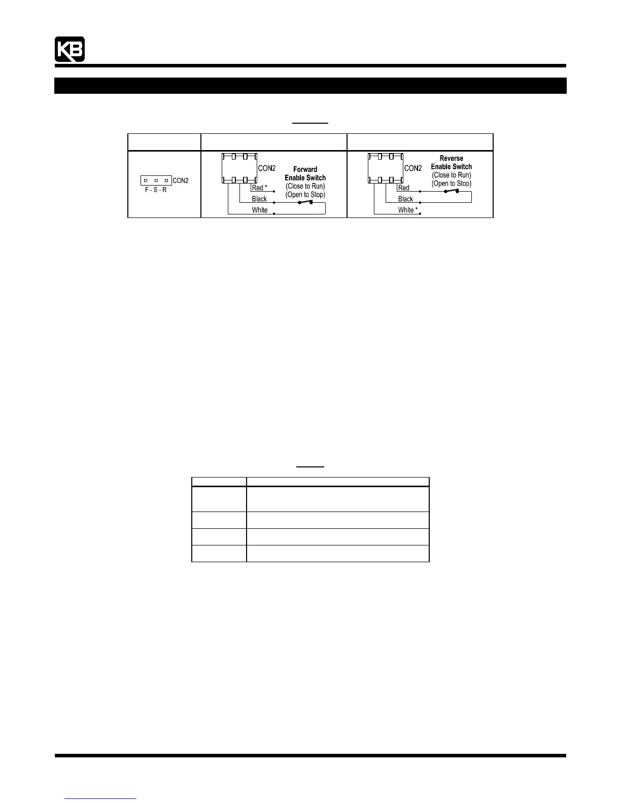
Figure 21
Enable Switch Connection
Jumper Removed
Connector Installed for
Forward Enable Switch
Connector Installed for
Reverse Enable Switch
* For Forward Enable Switch connection, the red wire is not used. For Reverse Enable Switch connection, the
white wire is not used. The unused wire must be insulated or it may be cut off at the connector.
10 AC LINE FUSING
This drive does not contain AC line fuses. Most electrical codes require that each ungrounded conductor contain circuit protection.
Do not fuse neutral or ground connections. It is recommended to install a fuse (Littelfuse 326, Buss ABC, or equivalent) or a circuit
breaker in series with each ungrounded conductor. Wire the drive in accordance with the National Electrical Code requirements and other
local codes that may apply to the application. Do not fuse motor leads. For the recommended fuse size, see
Table 1, on page XX.
11 DRIVE OPERATION
11.1 Start-Up Procedure: After the drive has been properly setup (jumpers and trimpots set to the desired positions) and wiring
completed, the startup procedure can begin. If the AC power has been properly brought to the drive, the power (PWR) LED will be
illuminated green. The status (ST) LED will indicate drive status, as described in
Section 11.2, on page XX. To remove and install
the Finger-Safe Cover, see
Section 5, on page XX.
11.2 Fault Recovery: The drive monitors for four faults (Undervoltage, Overvoltage, Short Circuit at the motor (phase-to-phase), I
2
t).
Table 3, on page XX, describes how the drive will automatically start (factory setting) after the fault has cleared.
Application Note: In Manual Start Mode, the drive must be manually reset for any fault. Use the Manual Start Switch, as
described in Section 9.6, on page XX. Also see Section 12.2, on page XX.
Table 3
Fault Recovery and Resetting the Drive*
Fault Automatic Start Mode (Factory Setting)
Undervoltage
Drive will automatically start
after the bus voltage returns to the operational level
or when the drive is first turned on (power up).
Overvoltage
Drive will automatically start
after the bus voltage returns to the operational level.
Short Circuit
Drive will automatically start
after the short circuit is removed.
I
2
t
Drive must be manually restarted.
See Section 11.2.1, on page XX.
* The fault must be cleared before the drive can be reset.
11.3 Restarting the Drive After an I
2
t Fault Has Cleared: The drive can be restarted after an I
2
t Fault has cleared by any of the
following methods.
Note: If an I
2
t Fault occurs, the motor may be overloaded. Check the motor current with an AC RMS responding ammeter. Also, the CL setting may
be set too low. See
Section 13.7, on page XX.
1 Disconnect and reconnect the AC power (approximately 15 seconds). The "ST" LED must change from quick flashing red to
flashing red/yellow.
2 Setting the Main Speed Potentiometer to zero (fully counterclockwise).
Note: In order to be able to reset the drive by setting the Main Speed Potentiometer to zero, it is necessary to have the MIN Trimpot set to zero
(fully counterclockwise).
3 Use the Enable switch or contact. See
Section 9.8, on page XX.