Do you have a question about the KB Electronics KBDA-24D and is the answer not in the manual?
Motors may overheat at low speed/high torque. Reduce load as speed decreases. Consult manufacturer.
Set Motor Current (Function No. 0.01) to match motor nameplate for overload protection.
Drive features modified 12t overload protection with Current Limit (CL) circuit.
WARNING: Disconnect main power before making connections. Risk of electric shock.
Installation/servicing by qualified personnel only. Eye protection, proper grounding required.
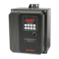
Description of KBDA drives: NEMA-4X/IP-65, washdown, for 3-phase AC motors up to 5 HP.
Includes current limit, 12t overload, Flux Vector Compensation, Power Start, Injection Braking, EICL.
Mount vertically on flat surface with ventilation. Allow space for connections.
WARNING: Do not use in explosion-proof applications. Ensure secure mounting.
WARNING: Disconnect power before connections. Ensure proper grounding.
Fuse ungrounded conductors, use disconnect switch, and liquidtight fittings for watertight integrity.
WARNING: Set Jumper J1 for correct input voltage to prevent catastrophic failure.
WARNING: Disconnect all AC line inputs from power before hi-pot testing.
After setup, press RUN to start. Factory set frequency is 05.00 Hz.
Keypad has 8 keys for programming. LEDs indicate drive status. See Table 6.
WARNING: LEDs/Display not guaranteed for power off. Ensure main power is off before servicing.
Lists 11 function groups covering motor, control, display, and communication parameters.
WARNING: LEDs/Display not guaranteed for power off. Ensure main power is off before servicing.
WARNING: LEDs/Display not guaranteed for power off. Ensure main power is off before servicing.
Connect maintained switch/contact to input terminals 1-7 and common to 8. Set Function 1.00 to "0001".
Connect momentary switches/contacts to input terminals 1-7. Connect common to terminal 8.
Use analog voltage, current, or PWM signal for motor speed control instead of keypad/potentiometer.
Connect Analog Input 1 to terminals 19 (signal) and 20 (common). Set Frequency Control to Analog Input 1.
Connect Analog Input 2 to terminals 21 (signal) and 22 (common). Set Frequency Control to Analog Input 2.
Connect Analog Output 1 to terminals 15 (signal) and 16 (common). Set Mode and Gain.
Connect Analog Output 2 to terminals 17 (signal) and 18 (common). Set Mode, Type, and Gain.
| Brand | KB Electronics |
|---|---|
| Model | KBDA-24D |
| Category | Controller |
| Language | English |