30
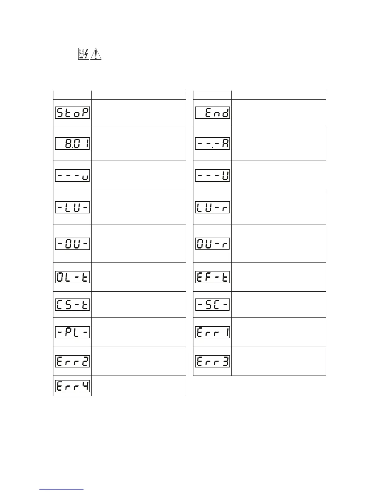
TABLE 7 – DIGITAL READOUT CODES
*Model KBDA-29: when used on 3-phase AC line input set for 7.0 Amps or higher (3 HP (2.25 kW)).
Display Description
Drive Stopped – Indicates that the drive is
in the Stop Mode.
Function No. 4.03 set to “0001”.
Function No. Example – A Function No.
consists of a Group No. (digits on the left
side of the decimal point) and a Group Code
No. (digits on the right side of the decimal
point).
Motor Voltage Display – When the display
is set to show Motor Voltage, the format will
be “XXXu”.
Function No. 4.05 set to “0001”.
Low Voltage Trip – Indicates that the AC
line input voltage is below the Undervoltage
Trip Point specified in Table 2, on page 9.
Overvoltage Trip – Indicates that the AC line
input voltage is above the Overvoltage Trip
Point specified in Table 2, on page 9.
Overload Trip (I
2
t Timeout) – Indicates that
the motor has been overloaded for an
extended period of time.
Current Source Trip – Indicates that the
current signal output (from the IODA) has
been opened.
AC Line Phase Loss Detection – Indicates
that the drive has detected a loss of one of
the phases in the 3-phase AC line input
applied to Models KBDA-29*, 45, 48.
Keypad Communication Error – Indicates
that the keypad failed to initialize when the
drive is powered up. This is an abnormal
condition – contact our Sales Department.
IODA Error – Indicates that the drive has
lost communication with the IODA.
Display Description
Parameter Changed – Momentarily flashes.
Indicates that a parameter has been suc-
cessfully changed.
Motor Current Display – When the display
is set to show Motor Current, the format will
be ”XX.XA”.
Function No. 4.04 set to “0001”.
Bus Voltage Display – When the display is
set to show Bus Voltage, the format will be
“XXXU”.
Function No. 4.06 set to “0001”.
Low Voltage Recovery – Indicates that a
Low Voltage Trip occurred and the AC line
input voltage has returned to within the
operating range specified in Table 2,
on page 9.
Overvoltage Recovery – Indicates that an
Overvoltage Trip occurred and the AC line
input voltage has returned to within the
operating range specified in Table 2, on
page 9.
External Fault Trip – Indicates that an
external fault has occurred at one of the
MFITs of the IODA.
Function Nos. 7.00 – 7.06 set to “0008”.
Short Circuit Fault – Indicates that the drive
detected a short circuit at the motor (phase-
to-phase).
Data Enter Error – Indicates that the drive is
in the Program Mode and a non-valid
parameter change has been attempted.
Flash Memory Error – Indicates that a flash
memory error on the drive has occurred.
This is an abnormal condition – contact our
Sales Department.
9.4 4-DIGIT DISPLAY – The 4-digit display provides readout of drive status, operating parameters, and
faults. See Table 7 for the Digital Readout Codes displayed and their descriptions.
WARNING! Do not depend on the LEDs or the 4-Digit Display to no longer be illu-
minated as a guaranteed power off condition. Be sure the main power switch or