29
*Function Nos. 4.04 – 4.06 set to “0001”.
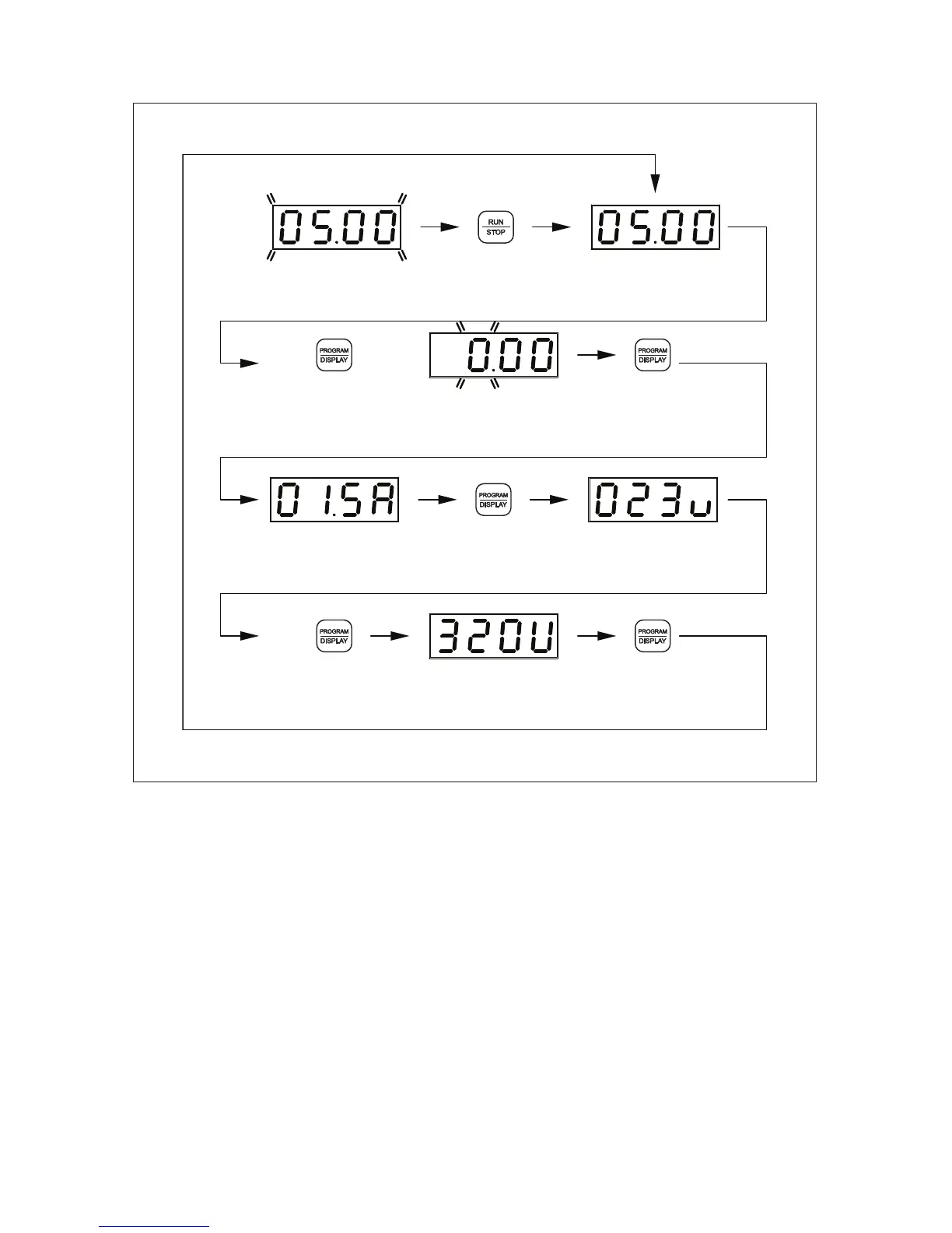
FIGURE 22 – FLOW CHART SHOWING MOTOR CURRENT, MOTOR VOLTAGE, AND BUS VOLTAGE
ADDED TO THE BASIC DISPLAY*
("FWD", "STOP", "Hz" LEDs On)
Set Frequency Flashes
POWER ON
Press Run Key
Set Frequency
("STOP" LED Off)to Run Drive
Motor Current Motor Voltage
("PGM" LED Off) to Change Display
Press Display Key
Press Display Key Group No
to Change Display Digit Flashes
("PGM" LED On)
to Change Display
Press Display Key
Bus Voltage
to Change Display
Press Display Key
to Change Display
Press Display Key