52
FORWARD MOTOR OPERATION
Analog Input 1 – Connect the potentiometer to Terminals “9” (+5 Volts), “19” (Analog Input 1), and “20”
(Common). Set Frequency Control (Function No. 2.00) to Analog Input 1 (“0002”).
Analog Input 2 – Connect the potentiometer to Terminals “9” (+5 Volts), “21” (Analog Input 2), and “22”
(Common). Set Frequency Control (Function No. 2.00) to Analog Input 2 (“0003”).
REVERSE MOTOR OPERATION
Analog Input 1 – Connect the potentiometer to Terminals “10” (-5 Volts), “19” (Analog Input 1), and
“20” (Common). Set Frequency Control (Function No. 2.00) to Analog Input 1 (“0002”).
Analog Input 2 – Connect the potentiometer to Terminals “10” (-5 Volts), “21” (Analog Input 2), and
“22” (Common). Set Frequency Control (Function No. 2.00) to Analog Input 2 (“0003”).
A11. MULTI-FUNCTION OUTPUT RELAYS
Two Multi-Function Output Relays are provided, which can be programmed for Run, Fault, Target
Frequency, Frequency Threshold Level (> 8.04 – 8.05), Frequency Threshold Level (< 8.04 + 8.05), I
2
t
or I•t Fault, Load Loss, External Fault, and Motor Overload. Relay 1 is factory programmed to operate
as a “Run” Relay (Function No. 8.00 set to “0000” (factory setting)). Relay 2 is factory programmed to
operate as a “Fault” Relay (Function No. 8.01 set to “0001” (factory setting)). The maximum allowable
contact load current is 2 Amps. See Figure 38, on page 53.
Note: If the drive “stops”, due to an External Fault Trip (“EF–t”), which indicates that a Multi-Function
Input Terminal (Function Nos. 7.00 – 7.06 set to “0008”) has closed, the Multi-Function Output Relay
Contacts will change state (when Function No. 8.00 or 8.01 is set to “0007”).
Multi-Function Output Relay 1 Contacts
Normally Open (N.O.) Contact: TB1 Terminal “23”.
Common (COM): TB1 Terminal “24” (contact common for Relay 1 only).
Normally Closed (N.C.) Contact: TB1 Terminal “25”.
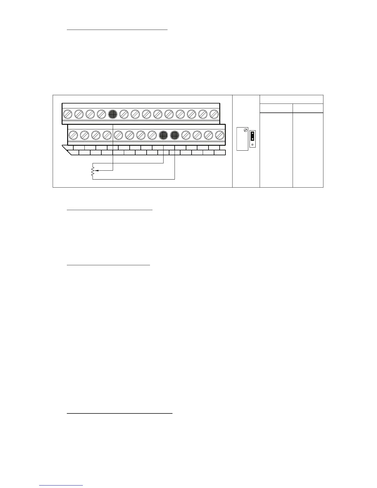
FIGURE 37 – BIDIRECTIONAL MOTOR OPERATION MAIN SPEED POTENTIOMETER CONNECTION AND FUNCTION SETTING
Function Setting
Function No. Code
2.00
Frequency
Control
0002
Analog
Signal 1
BIDIRECTIONAL MOTOR OPERATION (Use Analog Input 1 Only)
Connect the potentiometer to Terminals “9” (+5 Volts), “19” (Analog Input 1), and “10” (-5 Volts), as
shown in Figure 37. Set Frequency Control (Function No. 2.00) to Analog Input 1 (“0002”). In this
mode, the remote potentiometer is set for zero speed at 50% rotation. Rotating the potentiometer
clockwise will increase motor frequency in the forward direction. Rotating the potentiometer counter-
clockwise will increase motor frequency in the reverse direction.